Learn how intelligent purging systems work to extract non-condensable gases from an industrial ammonia refrigeration system.
Scroll down to watch the YouTube tutorial.
🎁 Check out the Danfoss Intelligent Purging System CLICK HERE
With its compact design, easy installation, and automatic purging functionality, the Danfoss Intelligent Purging System (IPS) helps improve the operational safety, efficiency, and cost-effectiveness of industrial refrigeration systems.
Learn more about the Danfoss IPS CLICK HERE
Industrial Refrigeration System Cycle
If we look at a typical single stage industrial ammonia refrigeration system, we have the compressor which pushes the high pressure ammonia vapour to the condenser. All the unwanted heat from the cooling space is removed from the refrigerant in the condenser and this heat is then dispersed to atmosphere.
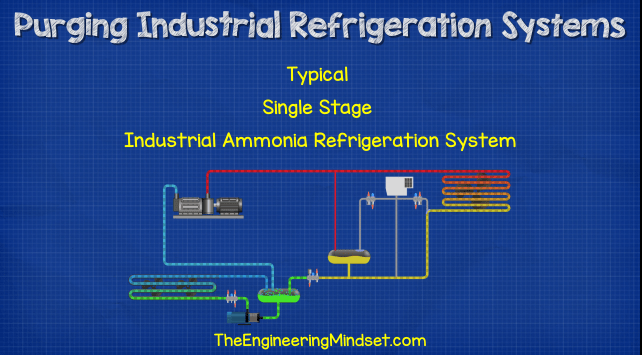
As the heat is removed the ammonia refrigerant condenses and converts to a liquid. This high pressure liquid refrigerant flows to the receiver and the expansion valve. The receiver holds a quantity of liquid refrigerant in temporary storage and will release or accumulate refrigerant here to stabilise changes in the cooling demands on the system. There is an equalizing line between the receiver and the compressor discharge line which, as the name suggests, equalizes the pressure between these two points in the system so that ammonia vapour can flow and therefore the liquid refrigerant level can vary.
The expansion valve regulates the pressure and addition of liquid refrigerant into the evaporator circuit. From the expansion valve the ammonia flows into the liquid separator. The liquid flows to the bottom where a pump typically sucks in the refrigerant and send this to the evaporator to provide cooling and collect the unwanted heat.
The ammonia pickups the unwanted heat from the evaporator and this will cause it to boil and evaporate. It leaves the evaporator and enters back into the liquid separator as a liquid / vapour mixture. The refrigerant which is liquid falls down and repeats the cycle again, but the refrigerant which is vapour rises and will be sucked into the compressor suction line. This low pressure vapour refrigerant is then compressed and sent around the system in a continuous cycle.
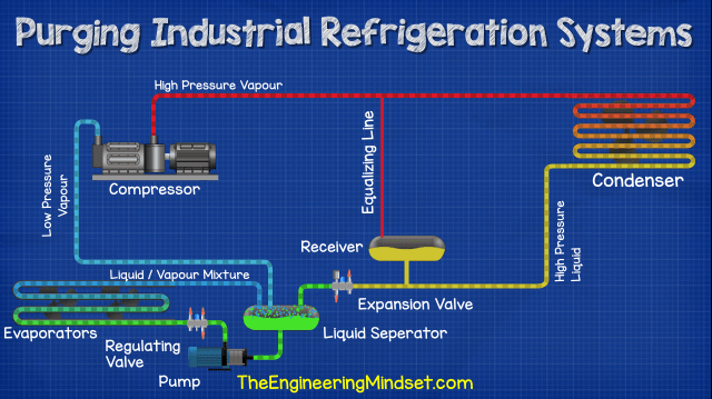
That’s our basic industrial ammonia refrigeration cycle. We’ve covered this in much greater detail in our previous article. To check that out CLICK HERE
Why Do We Need To Purge?
In this system we’re going to get a build up of non-condensable gases and air in two main locations. At the top of the receiver above the liquid refrigerant and at the top of the drop leg at the outlet of the condenser. These gases and pockets of air will decrease the systems efficiency therefore reducing the cooling capacity and increasing the energy consumption. It is inevitable that air will get into the system so we need to purge these to maintain optimal performance.
How Do We Do This?
What we do is connect the purging unit to both the locations where air and gases accumulate and control access to these with solenoid valves. We also have another pipe connected back to the liquid line, this will act as a drain and return any ammonia which is collected during the filtering.

Inside A Purging Unit
Let’s have a look inside the purging unit to see how it operates. We’ve just illustrated this a little different to make it easier to see.
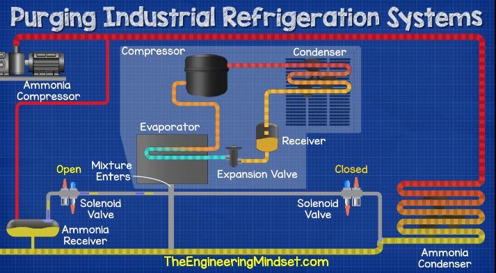
So as you can see inside the purging unit we have another, separated and much smaller, refrigeration system. We have a small compressor which is pushing a different refrigerant, R452A, around the separated circuit. It flows to a small condenser with its own fan which blows ambient air across the heat exchanger, the refrigerant then flows to a receiver, it then flows to an expansion valve, into an evaporator and back around to the compressor.
The evaporator is connected to the ammonia system. But the two systems are completely separated, the ammonia and the R452A never meet or mix.
The controller signals for one of the solenoid valves to open and vent the mixture of air, ammonia and non-condensable gases into the evaporator within the purging unit. Only one valve can open at a given time because if both open; then liquid refrigerant will rush in and flood the unit.
We’ve covered how solenoid valves work in detail in a separate article, to check that out CLICK HERE.
So with one of the solenoid valves open, lets say the receiver tank valve for example, then the mixture of air, ammonia vapour and other gases is going to seep out of the receiver tank and into the evaporator of the purge unit.
These vapours and gases will build up in the evaporator. The small refrigeration system is cycling the R452A refrigerant on the other side of the evaporator and will provide cooling to the gas mixture.
The mixture will be cooled down below the condensing temperature of the ammonia, this causes just the ammonia to condense into a liquid. The air and gases will remain in gas form because their properties are different and their condensing temperature is much lower. So the air and gases will remain in the evaporator while the ammonia turns into a liquid and this will then flow back via gravity into the system through the drain line. As this occurs, it naturally draws in more air, ammonia vapour and gases.
This continues until the build up of air and gases in the evaporator reaches a certain level. The controller detects that the evaporator temperature and pressure has changed as a result of the build up. So, it will open another solenoid on the vent line from the evaporator to discharge the build up of air and gases. This allows the air and gases to flow away into an external water bath to wash out any residual ammonia which might have been caught up. The process then repeats and we maintain the system at optimal performance.





Dear TEM, Why can we apply this thechnique to ammonia based systems and not regular refrigerant systems? Is it becouse of density of the fact that you may leak ammonia without consequense?
Thanks in advance!