

Do multimeters stress you out because they look complicated and hard to use with their giant user manuals, dials, settings, buttons, terminals and leads and there’s soooo many different versions too? How can anyone understand this? Well, they are actually quite easy and I’m going to show you how in this article.
You can even download my multimeter PDF book too and support the channel. Download it HERE.
Our sponsor for this article is PCBWAY, who offer everything from circuit boards, 3D printing, CNC machining, injection moulding, and even sheet metal fabrication. Do check them out HERE
Scroll to the bottom to watch the YouTube tutorial
Multimeter Options
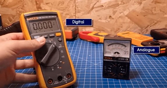
There are a lot of different multimeter designs. But, basically, we just have analogue and digital versions. Analogue multimeters use a dial, which, is horrible to use and difficult to read and they usually have just a few basic functions. Hardly anyone uses these anymore so I’m not going to cover them.
We’re going to use digital multimeters, which, have digital displays. These are precise, very easy to use and usually have a lot more functions.
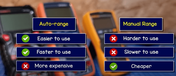
We have two main types of digital multimeter, manual range or auto-range. With auto range we just select the function and the multimeter will tell us the answer. With the manual range version, we have to select the correct range to get the correct answer. We’ll see how that works later in the article – but auto-range are the easiest and fastest to use, however, they are typically more expensive.
Here are my multimeter recommendations:
Professional Multimeter -➡️ https://amzn.to/3xu2Vaw
Good multimeter -➡️ https://amzn.to/3xrbuTd
All multimeters have the same basic functions of reading voltage, current and resistance. Different multimeters will have more advanced functions for things like capacitors, transistors, diodes, temperature etc. We will cover all of these, but, lets start with DC voltage.
DC voltage
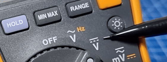
DC voltage is represented by this symbol. We find this type of electricity with batteries, solar panels and almost all your electronic devices. With DC, or direct current electricity, electrons flow in one direction. Think of it like the flow of water in a river. That’s why our osciliscope shows a straight line when we connect to a battery, and why we use this symbol.
We place the red lead into the V terminal and the black lead into the COM terminal. Then we connect the red probe to the positive and black probe to the negative terminal of the battery. On the auto-range multimeter we just select the DC voltage setting and it will instantly tell us the answer. If you see a negative number, you need to swap the leads over.
Here I’m testing a simple voltage divider circuit. we can see a reading of 0.031 volts. Which is 31 millivolts. We can switch to the millivolt setting for more precision. This particular device defaults to AC millivolts, and indicates we need to press the yellow button to switch the DC.
With the manual range version, we have to select the correct scale. That’s easy, we just select the next number up. For example, this battery is rated 12 volts, that’s higher than 2 but less than 20, so we use the 20 scale. This battery is rated 1.5V, that’s less than 2, so we use the 2 scale.
But what if we don’t know the voltage? How do we choose the correct scale? Well, that’s easy, we just start from the highest value and turn the dial until it changes to a 1. That means we have gone too far so we turn it back to the next position and that gives us the answer.
We can also measure voltages in a circuit. For example, here I have a basic prototype board with some resistors and an LED. I can read the total voltage of the circuit, by measuring across the positive and negative. I can also check the voltage at any point in the circuit. By connecting across individual components, we can check the voltage drop of that component, when it is powered.
Remember we can only measure the difference in voltages between two different points, if we try to measure the same point, we won’t read any voltage because there is no difference.
AC voltage
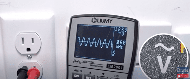
The electrical sockets in our homes provide AC or alternating current, this is different than DC electricity which we get from a battery. With AC the current alternates direction, flowing forwards and backwards. Think of it like the tide of the sea. So, our oscilloscope will show a sine wave for AC, which is why we use this symbol.
This is a much higher voltage than a battery. Electricity is dangerous and can be fatal, you should be qualified and competent to carry out any electrical work.
You can buy socket testers which will check your sockets, some will show you the voltage also. These are much safer, I recommend that you use these devices instead.
For AC voltage measurments, ensure our red lead is in the V terminal and the black lead is in the COM terminal. On the auto-range type, we simply select the AC voltage symbol.
Keep your fingers away from the tips, as these will become electrified. If you touch this, electricity can flow through you and shock you. Ensure the insulation on your cables is in perfect condition, never use or try to repair a damaged cable, buy anew one. Always connect the black wire to the neutral first because if you connect the red wire to an active terminal first, the black wire will instantly become electrified.
Do not use in wet conditions, wear rubber boots to insulate yourself and do not touch grounded surfaces while taking measurements.
For north American circuits, I’d recommend you flip the breaker first. We often find a safety screen over the terminal of the socket. We place the black probe into the large slot and the red probe into the small slot and push until the safety screen opens. When it is safe to do, Flip the breaker again and the meter will then read the value.
For british circuits, turn the switch off first. We also have a safety screen on these, place the red probe into the earth terminal and push down to disable this. Then we place the black lead into the neutral terminal, and the red lead into the live terminal. When safe to do so, flip the switch and the meter will read the value.
For Australian circuits, turn the switch off, push the black probe into the neutral terminal and then the red probe into the active terminal. When safe to do so, flip the switch, the meter will then read the value.
For European circuits, I would recommend you flip the breaker first. we need to place the probes into the terminals, apply some light pressure and tilt the leads to lift the safety screen and insert the terminals. Then flip the breaker again. We can reverse the probes and measure the voltage also with this system.
For manual range devices, we follow the same connection and safety procedure as the auto-range tutorial, but on our meter we select the next value up from the voltage we are reading. For example, on a 120V connection, we select the 200 setting. On a 230 volt connection, we select the 700 setting.
If you’re not sure of the voltage, start with the highest value first and turn the dial until the correct value is displayed. Do not exceed the maximum voltage of your meter. If the meter shows a 1, the reading is out of range and you will need to turn the dial to a higher setting.
Now you can get average RMS or true RMS multimeters. I’d highly recommend buying the True RMS type as this is more accurate. Electrical equipment can distort the waveform, only true RMS meters will accurately be able to measure this.
Don’t forget to check out PCBWAY for all of your 3D printing, CNC machining, injection moulding, and even sheet metal fabrication needs. Check them out HERE.
Resistance

Resistance is represented by this symbol and uses the unit of Ohms. It’s a measurement of how easily electrons can pass through something.
For example, electrons can flow very easily through this copper wire, which is why we use copper wire. However, it’s much harder to flow through this resistor, and it’s very very difficult to flow through rubber, which is why we use rubber insulation on wires to protect us from the electricity in the copper wire.
To measure resistance, we need to place our black lead into the com terminal and the red lead into the terminal with the ohms symbol.
With the auto-range device, simply turn the dial to the resistance setting and then connect your leads across the component. It doesn’t matter which side. The device will now display the results. We can test items like speakers, resistors, wires, potentiometers etc.
Pay attention to the letters on screen. This one shows just ohms. This one shows k ohms, meaning thousand ohms. This one shows M ohms, meaning mega or million ohms.
With the manual range, we need to select the correct setting. Remember, we use the next number up. For example, this resistor is rated 3 k ohm, that’s more than 2k so we go to the next value up, which is 20k and we can read the result.
This multimeter has a maximum setting of 2M, so if I try to read this 5.6M resistor, it will just show 1, because it is unable to measure values this large.
Be aware that resistance also changes with temperature. Resistors also have a tolerance. This one shows 3 kilo ohm, plus or minus 1%, so it could be anywhere between 3,030 30ms and 2,970 ohms. When we measure it, its 3,014 ohms, so this is within the stated tolerance. Other resistors like this one have a 5% tolerance.
However, this resistor is around 2 mega ohms. But, when we add it to the simple circuit, we get a reading of around 2 kilo ohms. That’s because it’s now in parallel and resistance divides. Do not try to test components on circuit boards, without isolating them first.
DC current
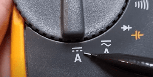
Current is a measurement of how many electrons are flowing through a particular point in a wire. Direct current means the electrons flow in one direction, we typically find this in battery operated equipment. It is measured in amps or amperes. This uses the symbol A, the dashed line represents direct current.
We must place the multimeter in series with the circuit. Either for the total circuit current, or branches of the circuit. Do not connect the meter in parallel with the load, this can cause a large current to flow through your meter and damage it.
Your meter will either have 3 or 4 terminals. One will likely show mA for milliamps, it should also state a number to indicate the mximum milliamp current it can measure through this terminal. This one for example states a maximum of 400 milliamps. If we know the circuit that we’re testing is below this, we can place the red lead into the terminal. Otherwise we must use the A terminal. This is usually stated as 10A, meaning a maximum of 10 amps, the time indicates for how long it can be connected. For example 10 amps for 10 seconds per 15 minutes.
Select the direct current setting, connect the red probe to the 10A terminal and the black probe to the COM terminal, then connect the red probe to the supply side and the black probe to complete the circuit and we get the result.
With the manual range, we need to select the correct setting. We already know this circuit is around 15 milliamp so we use the milliamp terminal and then choose the next highest value, which is 20 milliamp to get the result.
If we don’t know the current, we start by using the 10A terminal, select the highest setting and work our way down. Although here it shows 0.25 amps.
AC Current
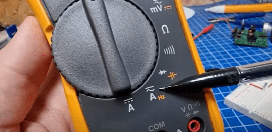
Alternating current means the electrons in the electrical system are constantly flowing backwards and forwards, we find this in our homes electrical system. It is measured in amps or amperes. This is represented by the letter A with a sine wave.
Remember electricity is dangerous and can be fatal. You should be qualified and competent to carry out any electrical work.
If you just want to measure AC current through a wire, I would recommend you instead use a clamp meter. This is much safer. Simply clamp around one wire and select the alternating current option. If you clamp the active and neutral wires together, the current will cancel each other out and you will not get an accurate reading.
If you need to measure the current of a device, buy an energy monitor plug instead and plug your device into this. It will safely show you the current, voltage and power.
If you absolutely must use a multimeter, then we have to connect the device in series with the circuit. The device has a very low internal resistance of perhaps just 0.2 ohms. Connecting in parallel will expose the meter to the full voltage of the circuit, instantly causing an enormous flow of current through your meter and destroying it.
The probes will become electrified along with any conductive surface they come into contact with. Be careful.
Check your meter has an AC current setting. If it doesn’t, then do not attempt to use it for this purpose. Next, check the terminal identification. Some will have a dedicated terminal for measuring milliamps and it will state the maximum current it can handle. If you know your circuit will exceed this, or you do not know the maximum current, then we need to use the terminal marked with an A, typically this will be labelled 10A indicating a maximum of 10 Amps can be connected, it usually tells you for how long, for example a maximum of 10 amps for 10 seconds and you must then disconnect it for 15 minutes to cool down. If you measure a lower current, you might be able to extend this time. Check the manufacturers guide.
Most meters come with a fuse to protect the device. This heats up and breaks the circuit if you exceed 10 Amps. You can check the fuse by connecting the red lead to the V terminal and placing the probe into the fused terminal and then selecting the resistance setting. If it displays a value of less than 0.5 it should be ok, if it states O.L then it is broken. You can remove the back cover the replace the fuse.
To use the multimeter, place your red probe into the 10A terminal, the black lead into the COM terminal and select the alternating current setting. Ensure the power is disconnected from the circuit. Connect the black probe to the load side and the red probe to the supply side, ensuring your meter is now in series. Check the area to ensure it is safe to turn the power back on. You will then see the results.
If you have a manual range meter, start with the highest setting, this is usually 10 amps. And it will display the result. If it shows less than 1 amp and the value is less than the next setting down, for example 0.15A, then you can change down a setting.
Continuity

We use the continuity function to test if two points in a circuit are connected, if so then it means electricity can flow.
Simply connect your black lead into the COM terminal and the red lead into the terminal with the continuity symbol. If it doesn’t show this, but does have the function, then use the V terminal.
The screen defaults to OL meaning open loop. Tap the leads together to test the meter. It should beep. Some display a light. It will display the resistance, usually in wires this is zero ohms or very close. We can use this to test a break in a circuit or wire. We can test that switches operate correctly and we can check fuses are also working correctly. We can test cables over very long distances by connecting one end together and testing the other end.
It’s important to now we can get false readings though, if we tried to test between these two points which are clearly broken, the meter will find an alternative route and indicate continuity. So you must consider this and isolate where possible.
Continuity tests do not work with high resistance circuits. For example this wire is fine. This low value resistor is also fine, but this high value resistor is too much and the meter indicates there isn’t continuity, even though there is.
Frequency

Frequency uses this symbol, this refers to how many times the pattern of an electrical signal repeats per second. For example, homes in north America use 60Hz and homes in Europe use 50hz. This just means the AC sine wave repeats 60 or 50 times per second. But we measure this in Hertz. This is all to do with the speed of the electrical generator. (3,600 or 3,000rpm).
Remember electricity is dangerous and can be fatal, you should be qualified and competent to carry out any electrical work.
To read frequency, we inset the red lead into the V terminal and black lead into the COM terminal. Then select the frequency function on the meter. Ensure you leads, equipment and working area is safe. I recommend turning the power off first. Do not touch the probe ends, wear rubber boots to insulate yourself and stay away from grounded surfaces. Then connect to the electrical system and turn the power on again. This will then show the frequency, depending on where in the world you are. Turn the power off before disconnecting.
This particular meter defaults to AC voltage and indicates we need to press the yellow button to take a frequency reading.
Diodes
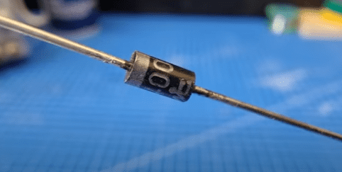
Diodes look something like this, they only allow current to flow in one direction. We use this symbol to represent them in engineering drawings.
To test them, turn the dial to the diode setting. Connect the red lead to the diode terminal, and the black lead to the COM terminal. If we connect the leads like this, we should read OL, because the diode had blocked the meter from taking a reading. When we reverse the leads, a value should appear. Typically between 0.5 and 0.8. If OL displays on both orientations, or a reading of around 0.4 appears in both directions, then the diode is faulty and needs replacing.
We can also check diodes with the resistance mode. We should see a value between 1 kilo ohm to 10 mega ohm, and reversing the connections we should see OL.
LED’s are also diodes, they just emit light. We can use the diode function to test these also, the LED’s should produce a very dim light. LED’s only light in one direction and block the current in the reverse direction. Higher voltage LED’s will not show a value.
Capacitors
Capacitors store and discharge electrons within a circuit, they are represented by these symbols. On the side of electrolytic capacitors it should state the rated capacity, the maximum voltage and also the negative terminal. Some types don’t display this, we would need to find the manufacturers datasheet.
Capacitors can store high voltages for a long time after being disconnected. Do not touch the lead as it will discharge through you.
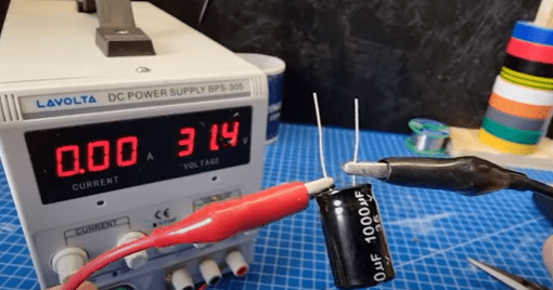
We can test the voltage of the capacitor by selecting the DC voltage setting, place the black wire into the COM terminal and the red wire into the V terminal. Then, carefully connect the probes to the capacitor, with the black probe touching the negative terminal of a polarised capacitor. Not all capacitors are polarised. The meter will now display the stored voltage.
If we see a reading of several volts or more, like this one, then we should place an appropriately sized resistor, across the terminals. This is a small capacitor so I will use a 2 kilo ohm, 0.25 watt resistor. We can see the stored energy is safely discharged.
Now select the capacitor setting, this particular model defaults to diodes and indicates we need to press the yellow button to switch to the capacitor setting. The black lead remains in the COM terminal and the red lead in the capacitor symbol terminal. Connect the black probe to the negative side, if polarised, and connect the red probe to the positive side. It will then display the result.
With non-polarised types we can use the probes on either side.
With a manual range meter we need to choose the appropriate setting. The value is usually stated on the side so we can select the next highest value from this on the meter. If you do not know the value, then start high and reduce until you see the result.
The result will probably not match the rated value. This one is slightly higher and this one is quite lower. So we need to consider if they are appropriate for our circuit and exchange them if needed.
Transistors
Transistors look like this and they are basically a type of electronic switch. They are represented by these symbols, although we use the hFE setting on a multimeter. To test them, we locate the identification number on the front and then find the datasheet for that. It tells us if it is a NPN or PNP type, which leg is the Base, emitter and collector and also the hFE value, which is the current gain.
Locate the transistor test area on the meter. Sometimes we need an adaptor like this one. We then select the hFE setting. We then align the transistor with the type, for example this is an NPN type so I use the NPN side, and then we insert the legs into the correct terminals. The meter then displays the result. This one is within range so it is good. If the meter shows a value outside of this range or just a 1, then the transistor is faulty.
If you don’t have an inbuilt transistor tester, then we can use the diode setting. Insert the red lead into the terminal with the diode symbol and the black lead into the COM terminal. Then insert your transistor into a test board. We know this one is an NPN type, so we place the red lead on the base pin, and we see a reading of around 0.6 – .0.7 when we connect to either the emitter or the collector. It should not give a reading if we test across the emitter and collector. Or, if we place the black probe on the base and test the emitter or the collector.
This one is a PNP type, so we need to place the black probe on the base pin. When we place the red probe on the emitter or the collector, we should see a reading between 0.6 – 0.7. We shouldn’t see a reading if we test across the emitter and collector. Or, if we place the red lead on the base pin and test the emitter and collector.
Temperature

This is the symbol for temperature reading, not all multimeters have this. It’s very simple to use, we find our temperature probe which typically looks like this; with the thermocouple at one end and the connectors at the opposite end. Ensure the connectors are inserted with the correct polarity. Place the black lead into the COM terminal and the red lead into the terminal marked with the temperature symbol, this one just says input, but we can use this terminal. Then select the temperature setting on the meter. It will then display the result. This one defaults to Celsius but we can change to Fahrenheit by pressing the button. This is used for air temperature or surface temperature only, do not use it in water.
Batteries
We need to test a battery in two ways. First, place your red lead into the V terminal and the black lead into the COM terminal. Then select the DC voltage setting. We connect the red probe to the positive terminal and the black probe to the negative. Then we see the voltage results. This battery is rated at 1.5 volts but when I test it we see 1.593 volts, because it’s brand new and fully charged.
This battery reads 1.07 volts, so the battery is dead. To fully test the battery, we need to take a resistor of around 100 ohms and connect this across the probes, then we connect the probes to the battery terminals, the current will flow through the resistor. The voltage should only drop slightly. This battery is rated at 1.5 volts, and under load it reads 1.547 volts, so this battery is good. This battery is also rated at 1.5 Volts, but when I test it with a resistor, the voltage drops to 0.86 volts, so this battery is not good and needs replacing.


")

")
