

In this article, we’re going to learn about how resistors work! We’ll explore the different types of resistors, how resistors work in circuits, and how to calculate resistance.
Scroll to the bottom to watch the YouTube tutorial
Why do resistors burst into flames, why are there so many different types, what do these stripes mean and how do resistors even work. I’m going to tell you in this article. You can even buy a mug or a hoody to support the channel, check them out HERE. This article is sponsored by PCBWAY, who offer everything from circuit boards, 3D printing, CNC machining, injection moulding and even sheet metal fabrication. Do check them out HERE.
What is a Resistor?
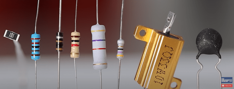
Resistors look something like this, they come in many shapes and sizes. They are represented with symbols like these in engineering drawings.
If we take this LED and connect it to a 9 volt battery, it will instantly be destroyed. Inside the LED is a thin wire and the battery will try to push so many electrons through this wire that it breaks. So, we use a resistor to reduce this current of electrons. The resistor is removing energy from the circuit to protect the LED, it literally turns the electrical energy into heat to remove it.
Resistors make it harder for electrons to flow. So, they add resistance to a circuit. Resistance is a measurement of how easily electrons can flow through a material, and we measure this in the unit of Ohms.
Many people incorrectly think the resistor acts like a speed bump, slowing the electrons down only momentarily. But they act more like a traffic jam, restricting how many electrons can flow, the speed of the electrons remains the same.
Think of water flowing through a pipe, it’s very easy to flow. But, if we partially block the pipe, we add resistance to the pipe, the water collides and so it’s harder for the water to flow and we also have a pressure drop across the restriction. Same with electricity, electrons can easily flow through a wire but if we add a resistor, then the electrons will collide so it’s harder to flow, and so the current is limited. We also have a voltage drop across the resistor. These collisions convert the kinetic energy into heat and that is why resistors become hot.
Most of you will recognise these types of resistors, the metal film resistor, carbon film resistor or the Carbon composite resistor. I’ll explain how these work later in the article and you can even try to make some circuits yourself.
These are all through hole type which we can plug into prototype boards or solder into printed circuit boards. Circuit boards typically label the components so we can identify their position.
We can buy them in bulk very cheaply, which is perfect for learning electronics and making mistakes. I’ll leave a link down below for where you can buy them.
These have a fixed resistance and on the side of the resistor we have these coloured stripes which indicate the resistance value. I’ll show you how to read that later in the article.
We also find SMD or surface mount device type, which are used for compact circuit boards. These are soldered directly onto metal pads on a circuit board. We can use a soldering iron or solder paste but some are so small they require a specialist machine. These have a fixed resistance and on the top is a number which indicates the resistance value. I’ll show you how to read that later in the article.
All of these have fixed resistance values but we can also have variable resistance types too.
We find manually adjustable versions like potentiometers, and rheostats which we can adjust using the dial. Some are very small and used for calibration of circuits.
Then we have automatic versions like thermistors, light dependant resistors, varistors etc.
All of these resistors will have a rated maximum resistance, voltage and power. The resistors will generate heat, and at a certain point they won’t be able to dissipate sufficient heat. The temperature increases so much that the protective layer catches fire and the resistor is then destroyed.
How Resistors Work
Lets look at how the different resistors work and their construction.
Carbon composite resistors are made by mixing a conducting material such as carbon or graphite with an insulating powder such as clay. This forms a solid core and we then place metal connectors at each end. This in enclosed within an insulating case. The electrons flow through the solid core. If we look inside one, we can see that there is a solid core with the metal connectors at each end and then the insulating case. Now these aren’t commonly used anymore, just because modern resistors have better performance, stability and they also last much longer.

Carbon film resistors are very common and are also very cheap to produce. They consist of a ceramic core which is coated in a thin layer of carbon, the metal connectors are attached with end caps and this is all covered with an insulating case. To control the resistance value, a helical groove is then cut into the layer of carbon. This creates a narrow path for the electrons and by changing the pitch of the helical cut, we can increase the length of the path and also reduce the width of the path, and so the resistance increases. Looking at these examples, we can clearly see the 1 ohm resistor has a short groove and wide path, the 1 kilo ohm has almost 3 rotations and the path is much thinner and then the 1 mega ohm resistor has almost 5 rotations with the path being very thin so the resistance is very high.
These are available in different sizes. The larger the resistor the more heat it can dissipate because of the larger surface area. So the bigger the resistor, the larger the power rating.
We usually find 4 stripes on these resistors which indicates the resistance value. The packaging usually tells us the resistance, or we can quickly measure it with a multimeter. However, sometimes we need to lookup the values using this chart. We have 2 digits, a multiplier and a tolerance band. The tolerance band is separated from the other stripes. We start with stripe 1 which is brown, so this is 1, the second stripe is black which is 0, the 3rd stripe is the multiplier which is brown so this is 10, therefore 1 and 0 are ten, multiplied by 10 gives us 100 ohms and the final stripe is the tolerance, this one is gold so it’s plus or minus 5% meaning it could be as low as 95 ohms or as high as 105 ohms. When I measure this one with a multimeter, we can see it is reading 98.2 ohms.
Ok, can you work out the resistance of this one by yourself? Tell me in the comments section and I’ll give you the answer at the end of the article.
Metal film resistors are very common, they consist of a ceramic core which is coated in a thin layer of metal, the electrical connectors are attached with end caps and this is all covered with a protective coating. The metal layer has a helical groove cut into it to increase the resistance, This increases the length of the path, and also reduces the thickness, which makes it harder for electrons to flow through, without colliding. So the resistance increases.
We can see this 10 ohm resistor has a very wide and short path so the resistance is low. If we compare it to this 1 mega ohm resistor which has a very thin and long path, so the resistance is very high.
This type of resistor has a high tolerance and very good stability so it is often preferred over the carbon film or carbon composite although it is slightly more expensive.
They are available in different power ratings, the larger the size the higher the rating and the more heat it can dissipate. The coloured stripes indicate the resistance level and we usually have 5 stripes on this type. The packaging normally tells us the resistance, or we can check with a multimeter. Otherwise we can use this chart to lookup the values. We have 3 digits, a multiplier and a tolerance band.
The first stripe is orange, which is 3, the second stripe is orange which is 3, the third stripe is black which is 0. Combine these numbers to get 330. the 4th stripe is the multiplier which is black and this is 1, so 330 multiplied by 1 is just 330 ohms. The 5th stripe is the tolerance, this is brown which means plus or minus 1% so it could be between 327 and 333 ohms.
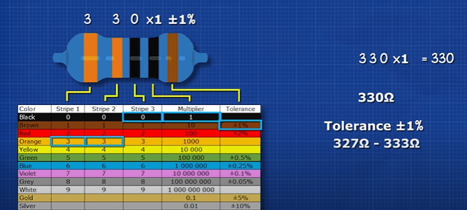
When I measure this one, it’s 329.9 ohms.
So can you work out the resistance of this one by yourself? Tell me your answer in the comments section and I’ll give you the answer towards the end of the article.
Wire wound resistors come in different designs. They offer very high power and current ratings. You can see they are very basic, just a wire wrapped around a ceramic core and are then covered with a thin layer of insulation. The thickness, length and material used dictates the resistance. This one shows it’s rated for 50 watts and 2 ohm.
Some are buried in a ceramic block with cement. but inside these, there is just a coil of resistive nichrome wire wrapped around a ceramic core with two end caps attached. These are used in high heat applications as the cement and ceramic layer protects the internal wire. This one shows it is rated for 10 watts and 10 ohms.
Another common example is this design, which uses an aluminium casing that helps dissipate lots of heat, these ridges increase the surface area so more unwanted heat can leave the resistor. There are holes in the casing so we can mount this to a surface. Inside we find a ceramic core with a coil of resistive nichrome wire between two electrical connectors. This typically has some form of insulation around it and then it is all enclosed within the metal housing with a resin end cap. This one shows it is rated for 10 watts and 33 ohms.
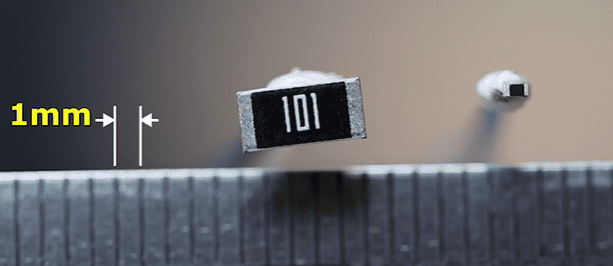
Surface mount device resistors are available in many sizes, some, like this one, are so small you need a microscope to see them. The construction is quite simple, we typically have a ceramic body with and electrode on each end, these are connected by a thin layer of resistive material and then covered with an insulating protective case and capped off with metal connectors. The resistive material has a grove cut into it with a laser, this reduces the area which electrons can flow so the resistance increases.
These provide high tolerance but they have a very low power rating. On the top are some numbers, this indicates the resistance value. With a 3 digit version, the first two digits represent the significant value and the third digit is the multiplier or how many zeros are after the significant value. For example, this one shows 2, 4, 0. The first two digits are 24 and we multiply this by 1, so this is just a 24 ohm resistor. This one is 1, 0, 1. So it is 10 multiplied by 10, making 100 ohms. This one shows 1,8,3. So it’s 18 multiplied by 1000 or 18 kilo ohm.
With 4 digit codes, the first 3 represent the significant values and the final value is the multiplier. This one shows 1, 0, 0, 0. So it’s 100, multiplied by 1, meaning it is a 100 ohm resistor. This one shows 3, 5, 0, 2. So this is a 35 kilo ohm resistor.
Sometimes we have the letter R before on between the values. We treat these as a decimal place. So this R56 resistor is 0.56 Ohms. This 47R5 resistor is 47.5 ohms.
We also find three-digit value versions with letters at the end. We have to look up these values on a table. We start by finding the first two values on the chart, in this case 26 which is 182, and then we find the letter, which is C- and that means multiply by 100, so this resistor is 18,200 ohms. This one shows 60 Z. So we look up 60, which equals 412 and Z means multiply by 0.001 so that gives us 0.412 ohms.
Potentiometers have a dial which lets us change the resistance. We have general use versions which we might use for example on volume control and then we have precision ones, which are used for tuning electronic circuits. We can see they have three terminals. Inside, we see there is a resistive track which runs between the two end pins and then a dial attaches from the track to the centre pin. Moving the dial increases the distance the electrons have to flow and so the resistance increases. We can connect it the opposite way also.
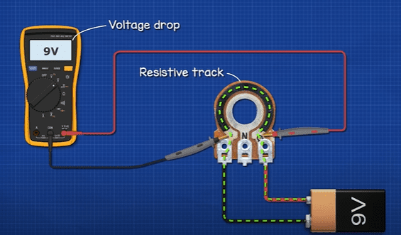
Like any resistor, we will have a voltage drop across the two end pins because of the resistive track. So, by connecting to the centre pin, we can use just part of this resistive track so we only have part of the voltage drop. This allows us to control the output voltage from this pin. Additionally, we can use just the centre pin and one end pin to create a rheostat, the total voltage drop now occurs between these two points so we control the current in the circuit like this.
On the front of these components we find a number, this indicates the maximum resistance. This one shows 1K so it’s 1 thousand ohms, this one shows 500k so it’s 500 thousand ohms. The letter indicates the type, B is very common and means the resistance changes in a linear way but we can get logarithmic types too.
These small versions have a 3-digit number, the first two are the significant numbers and the third tells us how many zeros to add. For example, this one shows 1, 0, 1. Meaning its 10 with 1 zero after, so it’s a 100 ohm resistor. That is the maximum rating. This one shows 2, 0, 4 so it is 200,000 ohms.
Rheostats are used to control current in a circuit, the current is typically large hence the size of the components. These are connected in series with the load. We only use two terminals at a time, even when 3 or 4 might be available. Smaller current circuits can use a potentiometer as a rheostat. The rheostat uses a resistive wire which is coiled around an insulating ceramic core which is typically an arc shape or cylindrical. The further the arm moves along the wire, the further the electrons will have to travel through the wire and so the higher the resistance will be.
We can see this one uses a raised surface on the sliding arm to make the connection to the coil, and this one uses a replaceable carbon brush with a flexible connection to the centre terminal.
On the side of the component we usually find the maximum resistance, maximum current or maximum power rating.
Fusible resistors look similar to a standard fixed value resistor. But when we overload a standard resistor it will burst into flames. However when we overload a fusible resistor, it heats up and then it breaks the circuit without bursting into flames. So it’s a resistor but it will act as a fuse to protect the circuit.
Inside this, we typically find a ceramic core with a resistive wire that spirals between the two end caps. This is then covered with a protective fire-resistant resin layer. The wire acts like a fuse wire and heats up, but at a certain temperature it will snap which then cuts the circuit. Other versions use a thin layer of metal alloy instead of a wire, and a groove is then cut into this layer to control the path that current can flow.
We can see this one has 5 bands, the last one is white which indicates it is a fusible resistor. The other 4 bands indicate the resistance. We can lookup the values using this chart, we see the first value is yellow which is 4, the second band is violet which is 7, the third band is black which is 1, so 47 multiplied by 1 is 47 ohms, and the 4th band is gold which is plus or minus 5%. So, it’s rated for 47 ohms but it could be anywhere from 44.65 to 49.35 ohms.

Varistors are variable resistors, although we can’t control them like a potentiometer. Instead, they automatically control their own resistance depending on the voltage of which they are exposed to. It looks very similar to a ceramic capacitor but acts slightly like a Schottky diode.
We typically connect it in parallel, across the supply for a delicate electrical circuit. Ordinarily, it might have a very high resistance, so it acts like an insulator and almost no current will flow through it. But, at a certain voltage, it will become a conductor and short to ground. This is very useful as it protects the circuit against voltage spikes.
Inside, we typically have a mixture of zinc metal oxide grains within a ceramic core. This is capped with metal plates and electrical connectors and then it is covered with an epoxy protective casing.
We can see this one has some digits on the front, the 14 indicates the diameter, the D indicates the shape, then we have 1, 2, 1. This means 12 with 1 zero after, so it is rated for 120 volts and the K indicates a tolerance of plus or minus 10% so it could be anywhere between 108 to 132 volts.
Thermistors are thermal resistors. We have NTC and PTC types. NTC will decrease in resistance as the temperature increases and PTC will increase in resistance as temperature increases. We can get them in film, Ceramic bead, Chip, Disc and glass encapsulated forms.
Their construction is quite simple. Just a layer of semiconductor between two conductors and this is covered with a protective coating. The semiconductor material acts as an insulator so the atoms hold on tightly to the electrons. But, as heat is applied, the thermal energy excites the electrons giving them enough energy to break free from the atoms so a current can flow. More heat means more electrons can flow, and so the resistance decreases.
These are very useful for inrush current limiting, temperature sensing, temperature control and the glass ones are good for high temperature applications.
Resistance temperature detectors are a simple temperature sensor, they typically consist of a ceramic core with a platinum wire wrapped around it, connected between two electrical connectors. And this is then covered with a protective coating. They are often fitted inside a metal case to measure liquid temperature.
Platinum is used because its resistance increases in a near linear pattern as temperature increases. So this makes calculations very easy.
When the wire is heated, the resistance increases. That’s because the atoms inside become excited and move around. This makes it harder for electrons to pass through without colliding so the resistance increases as temperature increases.
Light dependant resistors are variable resistors, they will automatically adjust their resistance depending on how much light they are exposed to.
They have a ceramic base which is coated with cadmium sulphide. This is then covered with two electrode plates, separated by a small gap. The electrical terminals connect to this and we usually find a clear protective coating covering the component.
Ordinarily they have a high resistance, the electrons within the cadmium are held in place by their atoms. But, when exposed to light, the photons will pass through the gap, they will hit the atoms of the cadmium and knock some electrons off. Another electron will take its place so a current develops. As the light increases, more electrons start to flow so the resistance decreases as light increases.
They come in a range of resistance values but they don’t typically have any markings on them, we only find this on the packaging. To identify them you have to test in complete darkness.
These are useful for automatic night lights and darkness sensor circuits.
Strain gauges look something like this. It’s a sensor which deforms under stress. We can see there is a layer of insulation and a thin conductive layer of foil looping in a grid pattern which provides a path for electricity. When at rest, we can see the strain gauge has a certain resistance. But, if we deform it this way, the resistance increase. And if we deform it this way it decreases. That’s because the material is stretching and contracting. So the length and width of the conductor is changing in very small amounts. Longer thinner wires have more resistance than shorter thicker ones. These are often used in Wheatstone bridge circuits to measure pressure, like in an electronic pressure switch.
Don’t forget to checkout PCBWAY for all of your 3d printing, cnc machining, injection moulding, and even sheet metal fabrication needs. Check them out HERE.
Why Do We Use Resistors?
Take a 9V battery, and using a test board, insert a 1 kilo ohm resistor and then connect the battery. Electrons are flowing from the battery and through the resistor. We should see a current of around 0.009 amps. We can calculate it like this. This gives us a power dissipation of 0.081 Watts, this is a 0.5 watt resistor it will work fine and generates a little heat.
But, if we connect a 10 ohm resistor, it will catch fire. That’s because the current is now around 0.9 Amps and so the power is around 8 Watts. This is only rated for 0.5 Watts so it rapidly overheats and catches fire.
So we can see that the higher the resistance the lower the current will be.
If we connect a red LED with a 470 ohm resistor to the 9 volt battery, the LED shines brightly. It doesn’t matter if we place the resistor before or after the LED, it will be the same.
The current is around 0.15 amps, the LED is dropping roughly 2 volts and the resistor is dropping a further 7 volts. The power dissipation is around 0.1 Watts.
If we use a 10 kilo ohm resistor, the LED is very dim. The current is around 0.0007 amps. But we still have a voltage drop of 2 volts on the LED and 7 volts on the resistor. The resistor is just limiting how many electrons can flow.
If we connect the LED with a 470 ohm resistor and then connect them to the centre pin of a 1 kilo ohm potentiometer. We can now dim the LED. This is acting as a rheostat, limiting the current. With the dial all the way to the left, the LED is at its brightest, there is almost no voltage drop over the potentiometer, the resistor has around 7 volts, and the led has roughly 2 volts. The current is around 0.015 amps.
With the dial all the way to the right, the LED is dim. The current is around 0.005 amps. We have a voltage drop of 1.9 volts on the LED, 2.2 volts over the resistor and 4.9 volts over the potentiometer.
So we can vary the resistance to control the current in the circuit.
We know that there is a voltage drop over a resistor. If we have two equal sized resistors in series the voltage drop will be same across each. So if we measure between the resistor and ground, we can access half the voltage and we have therefore created a voltage divider. The same current flows through both of them, but the voltage drop and power dissipation is different. It is being divided.
If we swap the first resistor for a 470 ohm resistor, we have a access to 6.1 volts. If we swap these over, we then only have access to 2.9 volts. So we can control the output voltage by controlling the resistor values. Or, we could use a potentiometer. The dial lets us use just part of the resistor so we have just part of the voltage drop.
We can also make a current divider by placing resistors in parallel. A single 470 ohm resistor will cause 0.019 Amps to flow. If we added a second in parallel, it would also pass 0.019 amps, they paths then combine so the total current would be around 0.38 amps. So we could either use one 235 ohm resistor or two 470 ohm resistors in parallel. The total current and power is the same, but in parallel the current and power is shared.


")

")

Wow what an amazing explanatory
big respect from Morocoo
This explanation is great stuff, is there anything I could buy online (a practice circuit board) for me to practice on?
great work