

Learn about electronics – without any electricity! Build mechanical circuits with Spintronics. Feel the pull of voltage and see the flow of current. Electronics is abstract, but Spintronics makes circuits tangible, irresistibly touchable, and deeply intuitive.
Scroll to the bottom to watch the YouTube tutorial
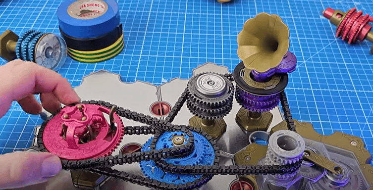
It’s here it’s finally here, look at this. It’s the spintronics game. How cool is this. Now they did sponsor the article but I personally bought this second kit as I liked it so much. Here’s why. This, is a transistor. There’s also a capacitor, an inductor, a resistor, a switch, an ammeter, junctions etc and it’s all powered by a mechanical battery.
We use a chain to transfer the batteries energy to the components and make mechanical versions of electrical circuits. The energy transfers from the battery, to the component and then back to the battery, just like an electrical circuit. I’m going to show you how to use them all and there’s even an online simulator. Check it out HERE.
Resistor
Electricity is hard to visualise because we can’t see electrons in the wire. But we can see how the chain moves. We can Add a blue link to make it even easier. We can also see and feel the voltage of the circuit, but I’ll show you that part later in the article.
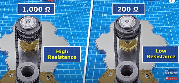
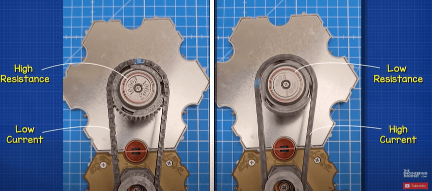
Notice that if I use this 1,000 ohm resistor, the chain turns slowly. But if I use this 200 ohm resistor, the chain can move much faster because the resistance is lower. Just like a larger current flows in a lower resistance electrical circuit. The speed of the chain represents the current.
If we remove the resistor, we get a short circuit. All the energy has returned to the battery without any resistance.
In electronics we can view the current with an ammeter, that won’t work with chains, so instead we use this device, which lets us hear the current. The lower the resistance, the higher the current and so the higher the pitch will be. A low current circuit will produce a low pitch.
Don’t worry, there’s a whole puzzle book with these kits which explains the components, provides tutorials and sets you challenges, the answers are in the back but don’t cheat. There’s also a beautifully illustrated storyline for you to follow, teaching you about electrical symbols, how circuits work and also giving you equivalent circuit diagrams.
Series circuit
This simple series circuit has a battery, a switch and a resistor. The switch lets us control the current. So if we connect the mechanical battery to the switch then the switch to the resistor we can control the chain using the switch. We could make the same circuit with just one chain also. The wire must come back to the battery to complete the circuit and the chain must also complete the circuit to work. In a series circuit, the current is the same anywhere in the circuit, and the chain is the same speed through all the components. If we add more resistance, the current reduces. So the chain moves slower.
Parallel circuit
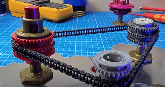
What about this parallel resistor circuit, how can we make that? Notice there is a junction in the circuit which divides the current. Well we have a mechanical junction too. So if we connect the battery to the junction and then we connect the first resistor and then the second. We now have a parallel circuit. Notice the chains are not the same speed. It’s slower on the high resistance circuit, just like less electrons flow in the electrical version. Parallel circuits divide the current.
If we added a resistor here, we would make a parallel series circuit. The power must flow from the battery to the junction then through either of the parallel resistors and then through the series resistor to get back to the battery. Same as if we had an electrical circuit.
Capacitor
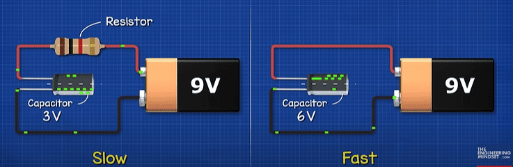
What about a capacitor? If we connect a battery to a capacitor it instantly charges to the battery voltage, then it stops because there’s nowhere for the electrons to flow to. Same happens when we connect the mechanical capacitor to the battery. The battery stops and we have stored energy in the capacitor. In this case the energy is stored within this spring, notice on top it shows 6 spin volts, because the battery is also 6 spin volts. We have to short the circuit to discharge the capacitor. We can slow the charging rate with a resistor, because the resistor limits the current. Same with the mechanical capacitor, it charges slower with the resistor connected. We could add a switch to control when the charging occurs. We just add a switch in series.
To discharge the capacitor, we need another path with a switch. By opening the first switch and closing the second switch the capacitor can discharge. Same with the mechanical circuit. But the capacitor discharges instantly. How can we stop that? We add another resistor. That slows the discharge rate down.
Voltage divider
You might know that when we place two equal sized resistors in series, we create a voltage divider. The voltage drop across both is equal, so when we measure the voltage between them and ground, we see half the voltage of the battery. So if we had two 500 ohm resistors in series, how can we measure the voltage? We just place a junction between them and then connect the capacitor to the junction. We see the voltage is 3 spin volts.
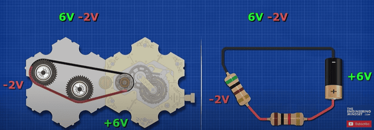
If we swapped resistor 2 for 1000 ohms, the voltage increases to 4 volts. If we instead swapped resistor 1 for 1000 ohms, we read 2 spin volts. The total always adds to the battery voltage. So if this resistor is losing 2 volts then the other must be losing 4 volts to make the 6 volts of the battery. This is Kirchoffs Law. The sum of all the voltages is zero. The battery provides 6 volts, this resistors subtracts 2 volts and this subtracts 4 volts.
Now if we place 3 resistors in series, sharing one chain. How can we measure the voltage drop of each resistor? We just swap the resistor for a junction. Connect the resistor to the junction, then connect the capacitor to the junction also. The resistors are all in series still, the junction sends power to the resistor and then back to the other resistors. The capacitor does exactly the same, so it’s in parallel with the resistor.
The battery provides 6 volts, the first resistor loses around 0.7 volts, so the chain here has around 5.3 volts. Then the 2nd resistor loses around 1.8 volts so the chain here is 3.5 volts, and the final resistor loses 3.5 volts, so the chain here is 0 volts. The total sum of the circuit voltage is zero. The larger the resistor the higher the voltage drop.
Remember voltage is a pushing force in a circuit, we often think of it like pressure.
So on the first 200 ohm resistor, if we remove the capacitor, and hold the top cog with our fingers we can feel a small pushing force. But if we try it with the 1000 ohm resistor, the force is much stronger because the voltage drop is much larger. So we can feel the voltage in the circuit and we can see the current represented by the speed of the chain.
Transistor
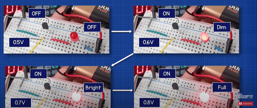
We also have this component, the transistor. A transistor is used to control other circuits. Here the LED is off, the transistor is blocking the current by providing a large resistance. But, when we apply a voltage to the control pin, the resistance reduces and allows current to flow, the LED turns on. The more voltage we apply, the lower the resistance will be. With the mechanical transistor, the top cog is the controller, the lower cog is the circuit we want to control. Instead of an LED we will use a resistor. Notice it doesn’t rotate until we apply a voltage or pressure to the top cog. The further we turn it, the faster it spins. That’s because the lower cog is connected to this rubber ring and these little arms are pushing against it, applying resistance like a brake pad. But as we turn the top cog, the arms are pulled inwards which lifts them off so the resistance reduces.
So how do we control the top cog. Well we could use a switch. But as soon as we apply voltage, it fully opens and then we can’t turn it off. It’s stuck open.
So we need to connect a resistor in parallel, so that when we turn the switch off, the transistor can discharge through the resistor.
For the control circuit, we will use a resistor and the speaker. But when we press the switch, it doesn’t turn on, that’s because we need a power supply to this section.
So we add a junction, then connect the resistor to the junction and also the switch. Now, when we press the switch, the transistor opens allowing current to flow through the speaker.
Inductor
We also have this component, the inductor. You can see that it stores rotational energy, and in spintronics that is current, whereas a capacitor stores pressure which is voltage. If we connect the inductor and switch in series, when I close the switch the inductor turns, it takes a moment to charge and get up to speed.
But, when I open the switch, the inductor destroys the circuit. It has to release it’s stored energy and has nowhere to go.
So we have to add a resistor in parallel with the inductor. That way it has a path to dissipate its energy.
Notice that both the resistor and the inductor rotate at the same time in the same direction. The inductor takes longer to reach top speed while it stores energy. The resistor is almost instantly at top speed. But when I open the switch, the resistor reverses direction, see how the chain reverses direction.
In the electrical circuit we can see that when I power the circuit the current flows through both components. It slowly increases through the inductor while it stores energy in its magnetic field. But, when I open the switch, the magnetic field begins to collapse and this pushes the electrons. They now flow through the resistor in the opposite way, to get back to the inductor. Just like we see the chain reverses in the mechanical circuit.
Diode
Now a diode is a device that only allows current to flow in one direction. But, it requires a small voltage to open and allow current to flow. We can make a diode from the transistor, by connecting it like this to the connector. When I apply a small force or voltage using my hands, the transistor opens and at that point the chain can move. But, if I reverse direction, the transistor closes, and the chain is blocked from moving. So, it acts just like a diode. To change direction we can change the lever position and it works in reverse.
Rectifier
The electrical sockets in out homes provide alternating current, where the current reverses direction so we have a positive and negative voltage. But, our electronics use direct current, where the current moves in one direction in the positive region. We need a rectifier to change from AC to DC. That uses just 2 diodes in a basic configuration. The output is rippled but only in the positive region, so it is a rought DC output, with an AC input.
If we connect two diodes from transistors like this, we have out AC input, but we get a rough DC output at the speaker. In electronics we can use capacitors to smooth out this ripple into smooth DC.
But we can also do that in spintronics too. The capacitors provide a low-pass filter. The speaker is much smoother now.
There’s so many incredible circuits we can build with the kits, I highly recommend you check it out HERE.

")
")


")


")

")