

In this article, we’ll explain LED technology in an easy to understand way. We’ll cover the different types of LED lights, the different colors that LEDs can emit, and the different applications for LED technology and how they work.
Scroll to the bottom to watch the YouTube tutorial.
Why does this LED produce a red light but this one produces a blue light?
When we apply a voltage across an LED, it produces light, it all comes from a tiny piece of semiconductor material inside, which is emitting energy as photons. BUT if we shine a light onto the LED, then we are firing photons back into it, so the process reverses and it will also produce a small voltage.
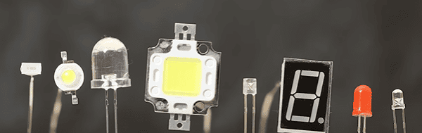
LED’s look something like this, they come in different shapes, colours and sizes for different applications. LED stands for light emitting diode. We use this symbol in engineering drawings for LED’s, notice it looks very similar to a diode symbol, except it has these arrows indicating that light is being emitted.
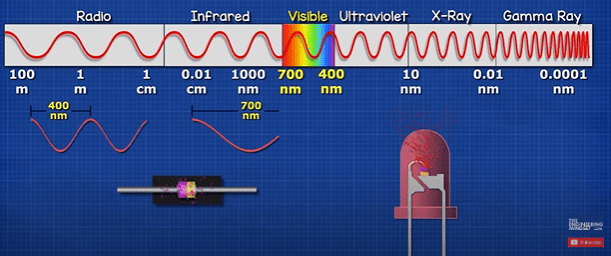
LED’s and diodes both work on the same principle, it’s just a semiconductor material in the middle of some electrical connectors. They both emit photons but only the LED emits photons in the range visible to humans. Which is when the photon has a wave length of round 400 to 700 nanometres. We perceive different colours depending on the wavelength of the photon in this range. FM radio signal is also a photon wave of around 3 meters, WIFI signal is smaller at around 6 centimetres A medical X-ray is tiny at around 0.01 nanometres but we can’t see any of these as they are outside the visible spectrum.
Have you ever noticed there’s an LED in your TV remote? This emits infrared light. The photon has a wave length typically around 940 nanometres, so humans can’t see it, but your phone camera can.
Inside the semiconductor, we just have electrons combining with holes and releasing photons in the process. We will learn in how it works in more detail later in the article.
Now, a standard diode uses different materials in its semiconductor layer which produce photons in the near-infrared range, these are absorbed by the casing and converted to heat so diodes become hot, but LED’s produce very little heat, unlike traditional incandescent lights which generate a lot of heat. In this design, the electrons collide with atoms in the filament and these collisions produce heat, the filament heats up so much it produces visible light. LED’s don’t need to produce heat to produce light, and so they are much more energy efficient.
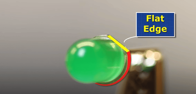
Most of you will recognise this type of LED, the 5 millimetre through hole type. But, have you ever noticed one side has a flat edge?
Through hole LED’s are perfect for learning electronics. They can be inserted into test boards or even soldered into printed circuit boards. We can get smaller 3-millimetre versions, or even larger 10-millimetre types. Typically, they are dome shaped but there are other shapes available like this square one.
We also get SMD type, which stands for surface mount device. These are soldered to circuit boards and allow compact designs. These versions are much smaller, some, like this one, are so small you need a microscope to solder them. We usually find SMD LED’s used in our light bulbs. This one is actually a blue LED, it just has a layer of yellow phosphorus over it, because yellow and blue combined makes a white light.
We can also get these very high-powered LED’s, which are basically lots of LED’s packed tightly together and are often used for torches and floodlights.
LED’s come in various different colour lenses, but we can also get transparent versions which emit different colour lights. The cases are only coloured to make it easy to tell what colour light is produced. It’s the materials used in the semiconductor layer that produces the different colours of light not the colour of the case. We will learn how that works later in the article.

LED’s only illuminate when we connect the anode lead to the positive and the cathode to the negative. Take a blue LED and a 3-volt coin battery, notice it only illuminates when connected a certain way.
It’s easy to identify the correct polarity, because the longest lead of the LED is the anode. But what if the LED leads have been trimmed? don’t worry, because one side of the LED’s case has a flat edge, and this indicates the cathode side. Additionally, inside we can notice there are two metal plates, the larger plate is the cathode.
With SMD led’s we find a small dot on the top, sometimes this is used to indicate the anode, other times for the cathode. So check the datasheet or test yourself. Here the LED illuminates when the positive it connected to the dot side. On the back we find a marking, but this again could mean either anode or cathode. Here we can see the LED illuminates when connected like this.
We can manually flash LED’s by using a switch, or we can use simply circuit like this resistor, capacitor and transistor circuit to automate this. Here is the schematic for that circuit.

But these blinking ones, will turn on and off by themselves automatically at a certain frequency.
There’s also this type, which change colour by themselves in a fast or slow transition. Inside is a tiny controller that sets the frequency. Here is the schematic for that circuit.
Then we have bi-directional leds. These can change between two colours. Inside are two LED’s connected in opposite ways. So, when current flows this way, one turns on and when current flows the other way, the other led turns on. Only one can be on at a time. This is the schematic for that circuit.
However, we can get these 3-pin bi-colour type. We can manually switch them between one colour, the other colour or both colours together. These have two led’s inside, which share a terminal. Here is the schematic for that circuit.
Then we have 4 pin RGB led’s. These have 3 separate led’s inside. A red, green and blue. These all share a terminal. We can activate separately, two at a time to mix the colours, or all three to produce white light. We can control the voltage and current to each led to make any colour we wish. Here is the schematic for that circuit.
If you look closely at your monitor, you can see the same thing is happening here too, lots of tiny multicolour LEDs.
Links for all these LED’s HERE:
Value pack LED➡️ https://amzn.to/3HiHI8L
3mm Transparent➡️ https://amzn.to/3VczCUV
5mm Transparent➡️ https://amzn.to/3NiXZ15
10mm ➡️ https://amzn.to/3oRSJaI
Bi-directional ➡️ https://amzn.to/449ww8e
Bi-color ➡️ https://amzn.to/3LBtFNY
Blinking LED ➡️ https://amzn.to/3LB12j1
Color changing ➡️ https://amzn.to/40OVBCD
RGB ➡️https://amzn.to/3oJ7dtg
SMD LED ➡️ https://amzn.to/449I8rR
Resistors ➡️ https://amzn.to/44fM9v0
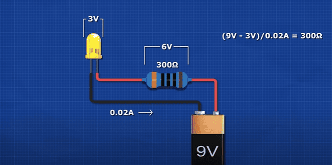
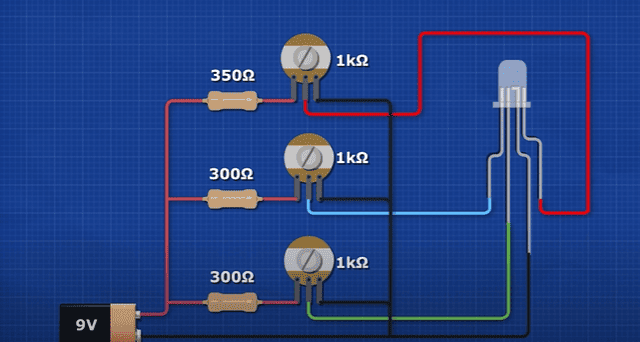
If we try to connect this LED to this 9V battery, it will instantly be destroyed. Inside the LED is a thin wire. The battery will try to push so many electrons through this wire, that it breaks. So, we use a resistor to reduce the current of electrons. The resistor removes energy from the circuit to protect the LED. It is literally turning the electrical energy into heat to remove it. The battery is providing 9 volts, the resistor removes around 7 volts and the led removes around 2 volts. The resistor is setting the current for the circuit. We can vary the current to control the brightness of the LED. But, when we vary the voltage supply, the current will also vary.
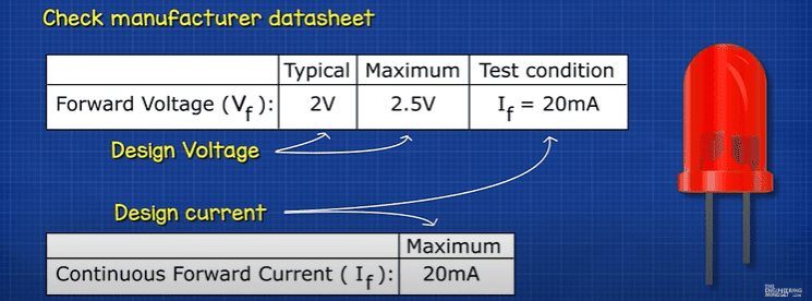
The manufacturers datasheet will tell us the rated voltage and current. This LED is rated for 20 milliamps, but we can go slightly above or below this and it will work fine. The lower we go the dimmer the LED will shine. But, if we go too high, the LED will be destroyed.
That’s why we find LED drivers inside light bulbs and also dedicated units powering strip lights. This lamp runs off 230 volts, the rectifier is changing the alternating current into direct current, the capacitor is smoothing this out, and this chip is providing a constant current to the LED’s so they don’t flicker.
This USB strip light is incredibly simple, the USB port provides a 5-volt rail and a ground rail, between them is just a resistor and an LED. Each set is connected in parallel so we can cut it to any length. The more LED’s we remove, the lower the current in the circuit.
Led’s can produce such bright lights we can see them from a distance. But wait who is that? Oh no, it’s a data broker. He’s copying all our online personal information and selling it for a profit. Luckily our sponsor SurfShark offers their incogni service to find and remove our information.
We all know that when we interact with apps and websites, we give away information like our location history, names and aliases, login credentials, social security number, phone numbers, search history and interests etc. These are all collected by data brokers to form an extensive profile about you and then sold.
For example, banks, credit and investment companies might buy information about your financial status, background and employment. Insurance companies might buy information about your health.
You can manually contact every data broker yourself, or you can use incogni to automate and track the process for you.
You can try it now, and the first 100 people to use my code ENGINEERINGMINDSET and this link will get 60% off: ➡️ https://incogni.com/engineeringmindset
When we look at an LED, we notice there are two metal leads which connect to the main body. The longest lead is the anode and the short lead is the cathode. The body is moulded from an epoxy resin, these are often coloured to make it easier to tell what colour the LED light is. On the side of the case is a flat edge which indicates the cathode side.
Looking inside the LED case, we see that both the anode and cathode leads each have a metal plate at the end, which are separated by a small gap. The plates stop the leads from turning. The larger plate also indicates the cathode side. On the cathode plate we typically find a cone shape, within the cone we find a small piece of semiconductor material made from a layer of N-type material with a P-type material on top. This forms a PN junction. A thin wire then runs between the anode terminal and the P-type material to complete the circuit.
When the LED is powered, photons are emitted from the PN junction of the semiconductor which produces the coloured light. The cone shape helps reflect the light out of the top of the LED case.
The colour of the light, depends of the wavelength of the photon emitted from the semiconductor and that depends on the materials used.
Electricity is the flow of electrons. Electrons flow easily through conductors like copper, but they can’t easily flow through insulators like rubber.
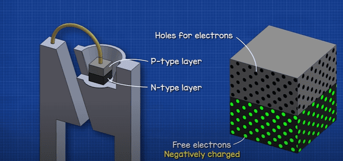
The N-type layer has lots of free electrons. The P-type layer is missing some electrons, but it has lots of holes that electrons can sit in. Electrons are negatively charged so the letter “N” just lets us know which side has a negative charge. As electrons are negative we consider the holes to be positive, so we use the letter “P”.
To make the semiconductor for a normal diode, we just use silicon. This has 4 electrons in it’s valance shell, the atoms will share these to become stable. So where do the electrons and holes come from? Well, we add some impurities like phosphorus which has 5 electrons in it’s valance shell, these are shared with the silicon atoms but it will leave one electron spare. This electron is free to move to other atoms. This is our N-type layer. For the P-type layer we add in some aluminium which only has 3 electrons in the valance shell, it doesn’t have enough to share with all it’s neighbouring atoms so there is a hole where an electron can move to. We now have a layer with too many electrons and a layer with not enough electrons. This join forms the PN junction. At this junction we get a depletion region. Some of the electrons move across to fill the holes and some of the holes move across, but this will create a barrier with a slightly positively charged region and a slightly negatively charged region. This creates an electric field which prevents more electrons moving across, when we connect a battery, electrons will flow and we call this the forward bias. But, If the voltage is too small, we can’t break the barrier.
With a normal diode, we can see the barrier is around 0.5 to 0.7 volts. This is the minimum voltage required for current to flow. But with a red LED it’s much higher, around 1.7 volts. The manufacturer will provide a chart like this which shows the forward current at a certain forward voltage. We see it starts at around 1.7 volts. We can see that at 2 volts we should see around 20 milliamperes of current. In this example, that’s exactly what we see.
Now, looking at a simple Bohr model of an atom. We have the nucleus at the centre which contains the protons and neutrons. Then we have a number of orbital shells where the electrons sit. Each shell can hold a certain number of electrons and the electrons need to have a certain energy to be accepted into the shell. The further the distance of the shell, the more energy is required. The outer most shell is the valance band. Just beyond this is the conduction band. Electrons that reach this band can break free from the atom. In a conductor like copper, the conduction band is very close so the electrons can easily move. But in an insulator like rubber the conduction band is too far away so the electrons can’t escape. But with a semiconductor like silicon, the conduction band is just a short distance away, so it acts as an insulator but when we apply a voltage the electron in the valance shell can break free.
In the silicon semiconductor, like a diode, the electron is jumping from the N-type conduction band, to the P-type valance band. The valance band has less energy than the conduction band, so the electrons need to lose some energy to be accepted into this lower band. It does that by releasing a photon. In silicon it needs to lose around 1.1 electron volts to be accepted. The energy of this photon is equal to a wavelength of around 1,127 nanometres. I’ll show you how to calculate that in a moment. That means silicon diodes emit near-infrared light which humans can’t see.
So, instead of silicon, scientists mixed Gallium and arsenic to form the semiconductor, then they add some impurities to this to form the N-type and P-type layers from this. This semiconductor has a larger band gap of around 1.424 electron volts, producing an 870 nanometer wavelength which is better but still too high. Then they tried Gallium Phosphide which had a bandgap of 2.26 electron volts resulting in a wavelength of 548 nanometers, which is perfect because the human eye can see this, and we see it as green. Then scientists realised that by blending a mixture of Gallium arsenic with Gallium Phosphide they could achieve any colour between these two points.
So if we mix 60% Gallium and arsenic with 40% Gallium Phosphide (GaAs0.6P0.4) we get around 1.7584 electron volts. = (0.6 x 1.424 eV) + (0.4 x 2.26 eV) = 1.7584 eV.
We can convert that to a wavelength using this formula: λ = hc/Eg.
λ = wavelength in meters, “h” is Planck’s constant 6.626 x 10^-34 J s, “c” is the speed of light in a vacuum 2.998 x 10^8 m/s, “Eg” is the bandgap energy of the material in electron volts, converted to joules 1.602 x 10^-19 J/eV.
So we drop these numbers in to get this equation
λ = (6.626 x 10^-34 J s x 2.998 x 10^8 m/s) / (1.7584 eV x 1.602 x 10^-19 J/eV)
and this gives us a wave length of roughly 705 nanometres, which produces a red light.
If we mixed 15% Gallium and arsenic and 85% Gallium Phosphide, this gives us 2.13 electron volts, which is a wavelength of 580 nanometres and this would give us yellow.
So mixing different materials together to form the semiconductor will create different coloured light. Once red, green and blue could be produced, we can mix these colours to produce any colour we need.


")

")
