

Learn how evaporators and controlled in industrial refrigeration systems, covering defrost, cooling, drip tray, valve stations, controller, liquid line, wet return line, hot gas line, vapour line, compressor, liquid separator, evaporator and much more.
Scroll to the bottom to watch the YouTube tutorial.
Industrial refrigeration systems are some of the largest and most complex in the world. These systems produce vast amounts of cooling and to achieve that they need lots of evaporators and each requires a number of complex looking valves.
Controlling these systems can be a challenge. Engineers need to ensure the system is operating effectively but also efficiently. To accomplish this, we need to be able to communicate with, and control, the various system components. So, how do we achieve that?
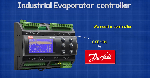
Well, we need a controller. This one is the EKE 400 by Danfoss who have kindly sponsored this article.
We’re going to look at the purpose of the controller, covering the basics of what it connects to in the system. But I’ve teamed up with Danfoss for this article, and they’re going to run you through the technical side with in-depth discussions around the functions and installation of the controller to help build your technical knowledge and understanding of not just controllers but also refrigeration systems. You can check that out here:
System
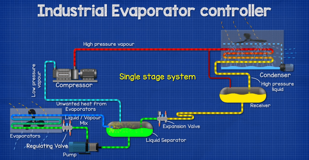
If we look at a single stage system, which is the simplest industrial refrigeration system, we can see we have the various system components such as the compressor, condenser, receiver, liquid separator and down in the corner we have the evaporator. We’re going to focus on this section in particular.
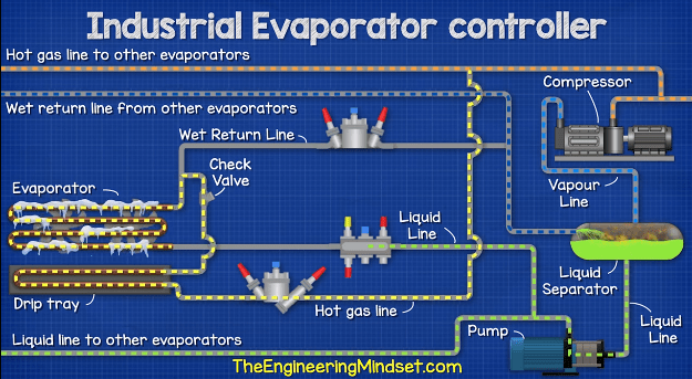
So, here we have a more detailed version of the evaporator circuit.

As you can see we have the evaporator and the fans which blow the ambient air across the heat exchanger of the evaporator to pickup the unwanted heat from the room and exchange this for cooling.
Then we have the liquid feed line. This comes in from the liquid separator and is circulated by a pump. The refrigerant is in a liquid state and flows through the valve station, and then into the evaporator. The refrigerant is kept within the walls of the tube inside the heat exchanger, it can’t escape to atmosphere and it doesn’t mix with the ambient air. While inside the evaporator, the refrigerant will pick up the unwanted heat, as it absorbs this heat it changes into a liquid and vapour mixture. The refrigerant then leaves the evaporator and flows through the wet return line, through another valve station and back to the liquid separator. From here the liquid will flow back to the pump while the vapour will flow back to the compressor.
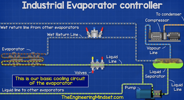
This is our basic cooling circuit of the evaporator. The refrigerant is pumped through the circuit to remove the unwanted heat and thus provide cooling.
Defrost
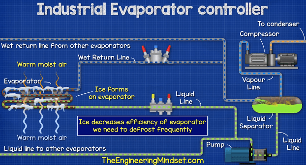
Due to the difference in temperature between the air and the refrigerant inside the evaporator, the air will condense and the moisture contained within the air will freeze to the heat exchanger. This decreases the efficiency of the heat exchanger, so every so often we need to defrost the evaporator.
So, we have another line coming in, this comes from the outlet of the compressor and branches off to feed the various evaporators. This high-pressure vapour refrigerant will pass through a valve station, through a drip tray and then through the evaporator in the opposite direction.
This effectively converts the evaporator into a condenser. The hot refrigerant is going to melt the ice and this collects in the drip tray, as we don’t want this to fall on the floor because it will freeze again very quickly.
As the refrigerant is exchanging its heat with the ice, the refrigerant will condense into a liquid. This liquid refrigerant will then leave the evaporator and flows into the liquid feed line. The feed line valve station is closed so the refrigerant flows into the defrost liquid drain line and another valve station controls the flow through here, typically using a float valve. From here it flows back into the wet return line and re-enters the liquid vapour separator where the refrigerant can either flow to the compressor or return to the evaporator.
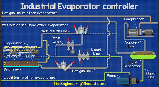
Once the defrost is complete, the valves reverse and cooling begins again.
So that’s our basic cooling circuit with a hot gas defrost.
Controller connections
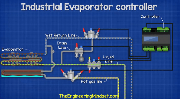
Now we need to be able to control all of these valves, as well as other components. This will allow optimal operation of the system as well as controlling the defrost cycle. So, our controller is installed and we run a few connection. First we connect to the solenoids valves in each of our valve stations, on the liquid line, wet return line, hot gas line and drain line. This will allow us to automatically control the position of each valve during normal operation and defrost cycle.
We can also use other methods of defrost such as electrical defrost, water/brine defrost as well as hot gas defrost by pressure control or liquid drain. But I won’t cover those in this article.
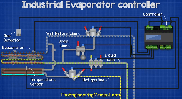
Next, we want to connect the evaporator fans to the controller also. This will let us control their rotational speed to suit the cooling demand. As we’re exchanging thermal energy we also need some feedback, so we will also connect a temperature sensor to the controllers. Additionally, we can also connect a gas detector to the controller for added safety.
By the way we have also covered the various types of industrial refrigeration systems in our previous articles. Do check those out HERE.
There are likely to be a number of evaporators in the refrigeration system, so we will need to install a controller for each individual unit. We can however connect each controller together, this will allow us to coordinate a defrost, it also allows us to use a centralised temperature sensor. Alternatively, we could connect the controllers to a PLC, this would allow us to remotely monitor each evaporator. Again, we can then coordinate the defrost via this method.
Once installed we need to consider the settings for when to activate the defrost, monitoring superheat, air temperature etc. This unit does come with an inbuilt wizard to speed up and simplify setup. But for this I’m going to divert you over to Danfoss for part 2 of this article HERE.
So, by using the controller we can:
- Reduce installation costs and time
- Achieve optimal cooling mode and safe defrost sequence
- Increase design flexibility
- Control valves and fans for individual evaporators
- And we can also change the units of measurement and language settings to suit the local installation.


")


")

")
