

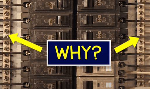
Why are ground and neutral wires separated in subpanels? When do we need a subpanel? When do we need a grounding electrode? and how are the panels connected? Lets find out.
Scroll to the bottom to watch the YouTube tutorial.
The electrical panel is where all our circuits get their power from. Each circuit has a circuit breaker, if we run out of space for a new breaker, then we need a sub-panel. Or, we can install one in another room where lots of circuits exist. That’s much easier to install than running multiple wires. Additionally, we can use a sub panel to provide power to an external structure. The sub panel is basically just an extension of the main panel. So, grab a pen and paper to make notes and a sip from your engineering mindset mug. Lets understand how the system works.
Remember electricity is dangerous and can be fatal, you should be qualified and competent to carry out any electrical work. You should also check with a local inspector to ensure compliance with regulations.
Electricity is generated at the power stations and then transmitted at high voltages over long distances to substations. Here, the voltage is reduced and the power is then distributed locally on power poles. A pole mounted transformer connects to this and reduces the voltage to a safer level for residential use.
Notice the power is distributed using three different phases, but our pole mounted transformer typically just connects to only one of these phases for residential properties.
We then find 3 wires or (service conductors) running from the transformer, to the property. These are two hot wires (or ungrounded conductors) and a neutral (or a grounded neutral conductor). This part is known as the service drop. They enter the property through a weather head (or service head) from here they run down to the electrical meter.
Inside the meter box, the neutral passes straight through but the two hot wires are separated by a gap. The electricity meter slots into this gap, providing a path across it, and it can then measure the current flowing through the hot wires to your property. You are then billed for this consumption of energy. Removing the meter while current is flowing can cause arcing which is very dangerous.
From the meter we have 3 typical scenarios.
- The wires run to a main panel, mounted externally
- They run to an internal main panel
- They run to an external disconnect and then to the main panel. The disconnect could also be built into the meter box.
In the first two scenarios, inside the main panel we first find a main breaker. Which looks something like this.
We can see there are two lug terminals on top, the two hot wires (or service conductors) will connect into these. Coming out of the main breaker are two separate hot bus bars. Which are these oddly shaped metal plates. Each hot wire connects to just one of these bus bars through the main breaker. In this case it is our main disconnect allowing us to energise or de-energise the entire home.
With scenario 3, our main disconnect is outside. We may or may not find another breaker in the main panel.
The main breaker is a double pole breaker, so both hot wires are connected or disconnected at the same time. We can manually flip this on or off. But it will automatically trip if we exceed the current rating printed on the latch. This provides our main overcurrent protection. Notice this one is just two 100 amp breakers tied together. That does not quite give us 200 amps though. Sure, you could provide 100 amps on each bus bar and have 200 amps combined. But, if just one of the bus bars uses over 100 amps, both breakers will trip together.
The panel will provide power to different circuits for lighting, receptacles, air conditioning etc. These are branch circuits.
Each branch circuit has a circuit breaker, which looks something like this. These simply hook into the casing, and then slot onto the protruding metal plates of the bus bars. We can place them on either side. Notice that if I use the top slot, on either side, it would connect to hot bus bar 1, where as slot two connects to hot bus bar 2.
We then run a hot wire (or ungrounded conductor) to power the load, for example a light fitting. The white neutral wire (or branch-circuit grounded conductor) then connects from the fittings and goes back to the neutral / ground bus bar, which looks something like this. Our service neutral or grounded conductor then connects to this bus bar.
We also find the ground wire (or equipment grounding conductor) running back to the main panel and connecting to all metal parts in that branch. The circuit is now complete, so we can control the light using the switch.
If we measure between either hot bus bar and neutral; we will read 120 volts. If we measure across both hot bus bars, then we read 240 volts.
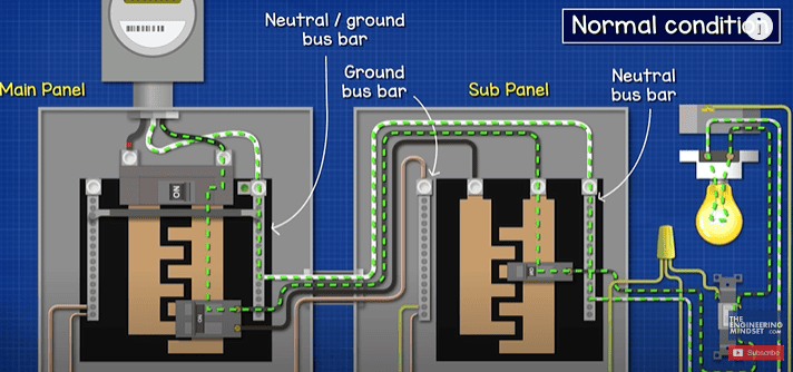
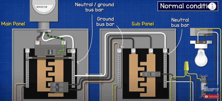
We typically have a bus bar on each side of the panel. On one of the bus bars we find a thick copper wire running down to a grounding electrode. This wire is therefore the grounding electrode conductor. The two bus bars are then joined in the main panel, if the service disconnect is located in there. So, these become neutral ground bus bars. We also find this green screw on the neutral bus bar. This is the main bonding jumper which connects the neutral to the metal casing. We will see why that’s important later in the video.
However, scenario 3 is different. The service hot wires connect to the main breaker. Then they connect to the hot bus bar lugs in the main panel. There may or may not be an additional disconnect here. From the circuit breaker the hot wire goes to the load, but the neutral comes back to a separate neutral bus bar which is not bonded to the metal case. The Ground wire also comes back to a separate bus bar. These travel back to the main disconnect box and both connect to the same bus bar, this is where we find the main bonding jumper. The service neutral connects to this bus bar. We also find a connection going down to the grounding electrode.
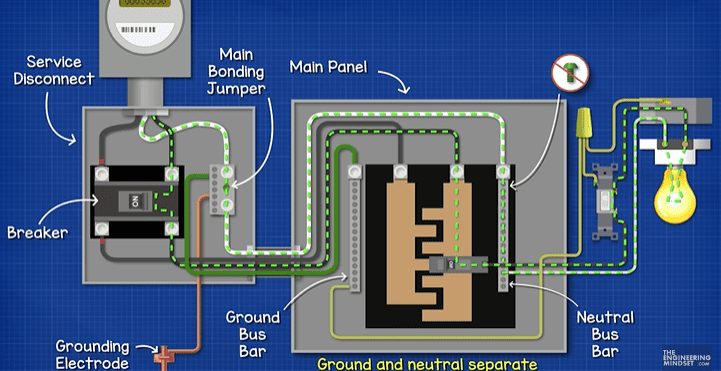
The current flows through the main breaker, through the main panel hot bus bars and then through the light fitting. It then travels back on the neutral to the dedicated neutral bus bar, and then back to the bus bar in the service disconnect. The ground and neutral do not connect in the main panel. Same as with a sub panel which we will see in just a moment.
For the subpanel. This will either be mounted next the main panel. In an additional room or in an external structure.
In each case we use a double pole breaker, which looks like this. This slots into the main panel and connects to both hot bus bars. This should be compatible and approved by the main panel manufacturer. From the breaker we have our two hot wires and these run to the sub panel and connect into the lugs of the two hot bus bars. Notice the sub panel doesn’t have a main breaker, it just has these lug connections. So, this is a Main lug panel board. The power disconnect and over current protection is controlled through the double pole breaker in the main panel in this example.
We then have our neutral conductor running from the neutral/ground bus bar and this connects to a dedicated neutral bus bar in the sub panel, this is not bonded to the metal casing. Then we have our equipment grounding conductor running from the neutral/ground bus bar over to a dedicated ground bus bar. This group of 4 wires travelling over to the subpanel are known as the feeder.
Where the sub panel will be installed in a separate building or structure, we need to install a grounding electrode and we connect it to the equipment grounding conductor terminal bus bar. However, if the panel is installed in the same property; then we do not need an additional grounding electrode.
Now, we can attach a circuit breaker to the panel and provide power to our loads. The neutral will come back and connect to the dedicated neutral terminal bus bar,
The ground wire will connect to the dedicated ground bus bar- otherwise known as the equipment grounding conductor terminal bus bar. This is bonded to the metal enclosure.
The neutral and ground wires must always be separated in the subpanel. But they can be connected in the main panel, if the main disconnect is located there. If the main disconnect is external, then they are separated in the main panel.
So lets find out what the reason is for that.
Why neutral and ground are separated in sub panels
Under normal conditions, the current will flow in from the service connection, through the main breaker, down the hot bus bar and out of the circuit breaker. It then travels on the feeder over to the sub panel, down the sub panel hot bus bar, out of the sub panel circuit breaker, to the load, then back to the sub panel neutral bus bar, then to the neutral/ground bus bar of the main panel and back to the transformer. Notice the ground wire isn’t used at all.
However, under a normal ground fault condition, where the hot wire touches the metal casing, the current will flow from the breaker, across the metal casing, back along the ground wire to the sub panel, then back to the main panel and from here it can get to the neutral to complete the circuit. As there is almost no resistance in this route, this will cause a huge and instantaneous surge in current, this would cause the breaker to trip and cut the circuit. That is why we must bond the neutral and ground together at main disconnect, this provides a complete circuit so the breaker can trip under a fault condition.
If the main bonding jumper was removed, so we had no connection between ground and neutral in the system, then when a ground fault occurs, where will the current flow? There’s no connection so all the metal parts become electrified. We might get some current flowing through the grounding electrode, maybe something like 4 amps or 10 amps for example, but if the breaker is rated for 20 amps then it will not trip.
However, if we accidently bonded the ground and neutral in the sub panel, and we also bonded it to the main disconnect, what will happen? Well the ground fault current would flow along the ground wire back to the main panel and out to the transformer. But, it will also flow in parallel back through the neutral from the sub panel, to the main panel and back to the transformer. If there was a metal raceway between the panels, the current will flow on this also. Or, If you touched both panels, it will flow through you as you now provide a path. So we definitely don’t want this occurring. We just want the fault current to flow in one wire which is the ground wire, back to the main panel.
If for some reason the neutral became disconnected on the subpanel, while it’s incorrectly bonded, then all the return current will flow on the ground wire back to the main panel. We do not want that. If we remove that incorrect bonding, then current can’t flow as there is no complete path now, so we know there is a problem with the circuit.
However, if we correctly bonded just the main disconnect, and then we lost the service neutral, what will happen? Well the rest of the circuit is fine, but we have a path from the neutral/ground bus bar, through the grounding electrode and back to the transformer. So we might get some current flowing here. As the case is bonded to the ground and neutral, it too becomes electrified. We would read a lower voltage because the load resistance and ground path resistance are now effectively a series circuit, and as you might know- voltage divides between resistors in series.
Additionally, if we have correctly bonded our system, but then we have a ground fault occur, while the service neutral is disconnected, then the ground fault current will flow to the neutral/ground bus bar but its only path is to the grounding electrode. Attached to this is the metal casing though, and as there is no resistance at the fault, the panel casing and all metal surfaces become 120 volts. There is a large resistance in the path between the grounding electrodes so some current might flow here. It might not be enough to trip the breaker.
To trip the breaker, we need a GFCI or ground fault circuit interrupter. This monitors the current flowing out on the hot and back on the neutral and if these two currents aren’t equal, the current must have found an alternative route so the breaker trips to cut the power.
")
")


")


 Pressure Enthalpy Chart")


")

")
