

Learn how Inductors work, where we use them, why we use them, the different types and why they’re important.
Scroll to the bottom to watch the YouTube tutorial.
Remember Electricity is dangerous and can be fatal, you should be qualified and competent to carry out any electrical work.
What Is An Inductor?
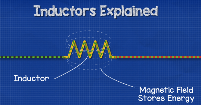
An inductor is a component in an electrical circuit which stores energy in its magnetic field. It can release this almost instantly. Being able to store and quickly release energy is a very important feature and that’s why we use them in all sorts of circuits.
In our previous article we looked at how capacitors work, to read it CLICK HERE.
How Does An Inductor Work?
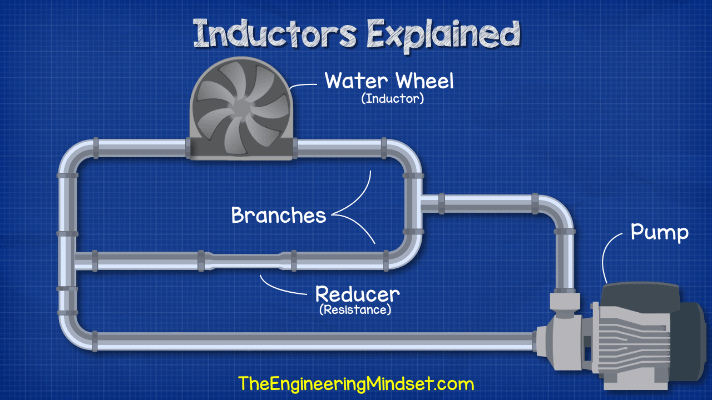
First, think about water flowing though some pipes. There is a pump pushing this water which is equivalent to our battery. The pipe splits into two branches, the pipes are the equivalent to our wires. One branch has a pipe with a reducer in it, that reduction makes it a little hard for water to flow through, so it’s equivalent to resistance in an electrical circuit.
The other branch has a water wheel built in. The water wheel can rotate and the water flowing through it will cause it to rotate. The wheel is very heavy though so it takes some time to get up to speed and the water has to keep pushing against it to get it to move. This is equivalent to our inductor.
When we first start the pump, the water is going to flow and it wants to get back to the pump as this is a closed loop, just like when electrons leave the battery they flow to try and get back to the other side of the battery.
Please note- in these animations we use electron flow which is from negative to positive but you might be used to seeing conventional flow which is from positive to negative. Just be aware of the two and which one we’re using.
As the water flows; it reaches the branches and has to decide which path to take. The water pushes against the wheel, but the wheel is going to take some time to get moving and so it’s adding a lot of resistance to the pipe making it too difficult for water to flow through this path, therefore the water will instead take the path of the reducer because it can flow straight through and get back to the pump much easier.
As the water keeps pushing, the wheel will begin to turn faster and faster until it reaches its maximum speed. Now the wheel doesn’t provide almost any resistance so the water can flow through this path much easier than the reducer path. The water will pretty much stop flowing through the reducer and will all flow through the water wheel.
When we turn off the pump, no more water will enter the system, but the water wheel is going so fast it can’t just stop, it has inertia. As it keeps rotating it will now push the water and act like a pump. The water will flow around the loop back on its self until the resistance of the pipes and the reducer slows the water down enough that the wheel stops spinning.
We can therefore turn the pump on and off and the water wheel will keep the water moving for a short duration during the interruptions.
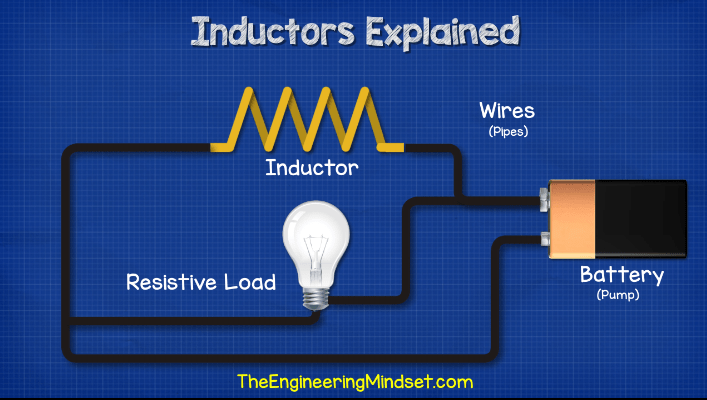
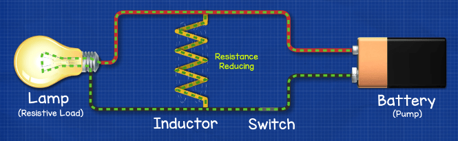
We get a very similar scenario when we connect an inductor in parallel with a resistive load such as a lamp.
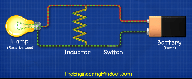
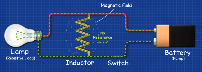
When we power the circuit, the electrons are going to first flow through the lamp and power it, very little current will flow through the inductor because its resistance, at first, is too large. The resistance will reduce and allow more current to flow. Eventually the inductor provides nearly no resistance so the electrons will prefer to take this path back to the power source and the lamp will turn off.
When we disconnect the power supply, the inductor is going to continue pushing electrons around in a loop and through the lamp until the resistance dissipates the energy.
What’s Happening In The Inductor For It To Act Like This?
When we pass electrical current through a wire, the wire will generate a magnetic field around it. We can see this by placing compasses around the wire, when we pass current through the wire the compasses will move and align with the magnetic field.

When we reverse the direction of the current; the magnetic field reverses and so the compasses also reverse direction to align with this. The more current we pass through a wire, the larger the magnetic field becomes.

When we wrap the wire into a coil, each wire again produces a magnetic field but now they will all merge together and form a larger more powerful magnetic field.

We can see the magnetic field of a magnet just by sprinkling some iron filings over a magnet which reveals the magnetic flux lines.

When the electricity supply is off; no magnetic field exists, but when we connect the power supply, current will begin to flow through the coil so a magnetic field will begin to form and increase in size up to its maximum size.
The magnetic field is storing energy. When the power is cut, the magnetic field will begin to collapse and so the magnetic field will be converted into electrical energy and this pushes the electrons along.
In reality it’s going to happen incredibly fast, we’ve just slowed the animations down to make it easier to see and understand.
Why Does It Do This?
Inductors don’t like a change in current, they want everything to remain the same. When the current increases they try to stop it with an opposing force. When current decreases they try to stop it by pushing electrons out to try and keep it the same as it was.
So when the circuit goes from off to on, there will be a change in current, it has increased. The inductor is going to try to stop this so it creates an opposing force known as a back EMF or electromotive force which opposes the force which created it. In this case the current is flowing through the inductor from the battery. Some current is still going to flow through, and as it does, it generates a magnetic field which will gradually increase. As it increases more and more current will flow through the inductor and the back EMF will fade away. The magnetic field will reach its maximum and the current stabilises. The inductor no longer resists the flow of current and acts like a normal piece of wire. This creates a very easy path for the electrons to flow back to the battery, much easier than flowing through the lamp, so the electrons will flow through the inductor and the lamp will no longer shine.
When we cut the power, the inductor realises there has been a reduction in current. It doesn’t like this and tries to keep it constant, so it will push electrons out to try and stabilise it, this will power the light up. Remember, the magnetic field has stored energy from the electrons flowing through it and will convert this back into electrical energy to try and stabilise the current flow, but the magnetic field will only exist when current passes through the wire and so as the current decreases from the resistance of the circuit, the magnetic field collapses until it no longer provides any power.
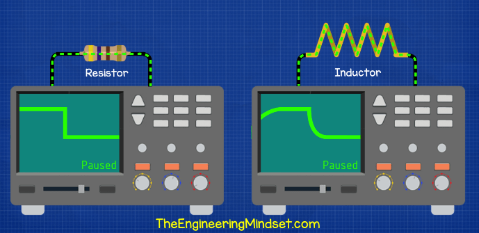
If we connected a resistor and an inductor in separate circuits to an oscilloscope, we can visually see the effects. When no current flows the line is constant and flat at zero. But when we pass current through the resistor, we get an instant vertical plot straight up and then it flat lines and continues at a certain value. However, when we connect an inductor and pass current through it, it will not instantly rise up, it will gradually increase and form a curved profile, eventually continuing at a flat rate.
When we stop the current through the resistor, it again instantly drops and we get this sudden and vertical line back to zero. But when we stop the current through the inductor, the current continues and we get another curved profile down to zero. This shows us how the inductor resists the initial increase and also tries to prevent the decrease.
By the way we’ve covered current in detail in a previous article, do check that out HERE.
What Do Inductors Look Like?
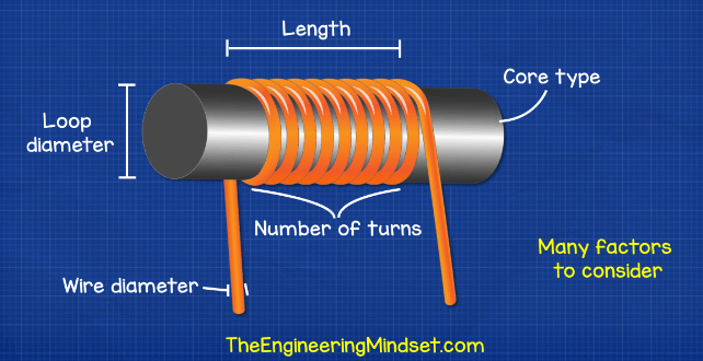
Inductors in circuit boards will look something like below.
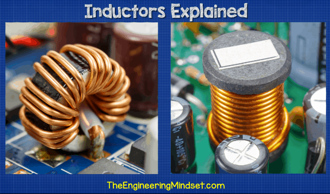
Basically, just some copper wire wrapped around a cylinder or a ring. We do get other designs which have some casing over, this is usually to shield its magnetic field and prevent this from interfering with other components.
We will see inductors represented on engineering drawings with symbols like these.
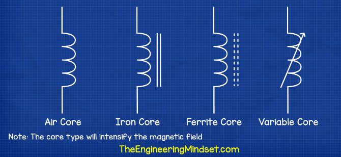
Something to remember is that everything with a coiled wire will act as an inductor that includes motors, transformers and relays.
What Do We Use Inductors For?
- We use them in boost converters to increase the DC output voltage while decreasing the current.
- We can use them to choke an AC supply and allow only DC to pass.
- We use them to filter and separate different frequencies.
- We also use them for transformers, motors and relays.
How To Measure Inductance
We measure the inductance of an inductor in the unit of Henry, the larger the number; the higher the inductance. The higher the inductance; the more energy we can store and provide, it will also take longer for the magnetic field to build and the back EMF will take longer to overcome.
You can’t measure inductance with a standard multimeter although you can get some models with this function built in, but it won’t give the most accurate result, that might be ok for you it depends what you’re using it for. To measure inductance accurately, we need to use an RLC meter. We simply connect the inductor to the unit and it will run a quick test to measure the values.


 Pressure Enthalpy Chart")


")


")

")

If you get to see the passage of the river in the canal, then you are an engineer .. electricity .
Article and video both are helpful
What a great article. Very well written and was super easy to understand. Thank you for this!
[…] have covered inductors, diodes and transistors in detail in our previous articles HERE- Inductors, Diodes, […]
I’m a bachelor Moroccan studying and as known i’m suffering day by day with the difficulty of understanding and having knowledge with this poor Moroccan educational programs i’ve discovered you first in YouTube and i’ve recommended you all my colleagues to start watching you and i just want to tell you keep going your the best teacher i’ve ever had
Normally our teacher is spending 4 hours or even more to explain RC circuit and in spite of that i do not understand. In your 10 min’s video i can have much more informations better explainned and in a very short time. if you’re not having enough amount from your work be aware that you’re helping lot of students to succeed and that’s more important than money “paradise”!!
what an interesting study every day i got new skills with busy time how ever everything is amazing thrugh the class with all supporting doc including vidios and always no tired you help all the students any time..
I am seeking information about an inductor that was “fried” (pretty much melted!) on the circuit board (L-1). It is a 4 pin inductor with the coil divided by several ceramic strips. The core is mounted horizontally and appears to be a coupled or non coupled inductor. )///(
It is about 1 1/2 centimeters wide including the ceramic insulators/separators.
I do not have access to the data sheet, but the code on the top rail of the core [ ] is marked ” CE 24 V0227M00 A9 and 2912/40/21/2000. This is on a circuit board on an AC V ECM circulator.
I have already replaced the entire circulator (pump), but I am curious as to the ID of the inductor. “Asking for a friend.”