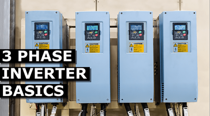
In this article, we’re going to learn the basics of a 3 Phase Rectifier. This rectifier is used in power supplies and can be a major part of your electrical engineering education.
Scroll to the bottom to watch the YouTube tutorial
We will consider the first part of the VFD which is the rectifier.
In this part we find six diodes in parallel. I’ll title these one to six.
Each of the three phases is connected to one pair of diodes. As we know electricity needs to get back to its source to complete the circuit. So in this setup the current will flow through the load and back to the source using another phase. Remember it can do this because the current in each phase flows forwards and backwards at a different time. We’ll see this in detail in a just moment.
The load can be anything – a lamp, a motor or an entire circuit. In this case it will just represent the rest of our VFD circuit. The electricity will continue to alternate in the supply of phases but the diodes will only allow the peak phase to pass and will block the others. So I’m just going to animate these ones. Ok lets see this in action. Phase 1 is first. This comes in and can only flow in one direction which is through diode one. It then passes through the load. Once the current passes through the load it will then need to get back to the source and as phase 2 is in the negative half of the cycle the current will flow through diode 6 into phase 2. In the next segment we see the current is still flowing in phase 1 and diode 1 but now phase 3 is in its negative half so the current switches and the flow returns through this phase via diode 2.
In the next segment phase 2 is approaching its peak so the current now flows through this phase and through diode 3. It then flows through the load and back into phase 3 via diode 2. In the next segment the current flow is still in phase 2 via diode 3 but phase 1 is now at its negative peak so the current will flow through diode 4 back into phase 1.
In the next segment we see that phase 3 is now approaching its positive peak so the current flows through this phase by diode 5. It then flows through the load and returns via diode 4 into phase 1. Finally the current flows through phase 3 via diode 5 through the load and then back into phase 2 via diode 6. This cycle just repeats constantly like this. The oscilloscope for the three phase supplier will see three sine waves for the AC electricity. But the oscilloscope on the load will see this as a rough C electricity with some ripples in it. Now we need to smooth out those ripples to clean up the DC electricity. For this we connect a capacitor across the positive and the negative. This capacitor is like a storage and will absorb electrons when there is excess and it will release electrons when there is a reduction. This will therefore smooth out the ripples in the DC electricity to a nice smooth signal on the oscilloscope.
We have covered how capacitors work previously, you can check out the article HERE.
Now that we have clean DC we are ready to turn that back into precisely controlled AC at variable frequency. And for that we need an inverter. An inverter is basically a number of JGVT’s which are switches that can turn on and off super fast. Im going to animate this using some simple switches instead of IGBT’s just to make it easier to visualize.
Ill number these switches as follows.
To get our three phases we need to open and close switches in pairs to direct the flow of current form our supply and return path. That way the connected motor will experience alternating current. Remember AC is where the current reverses. So if we took a lamp and connected it to some switches and a DC power source, we can control the directional current through the lamp by opening and closing switches in the right order. Therefore the lamp experiences alternating current even though its coming from a DC supply. For the three phase supply we time the switches to simulate the three phases. Lets see how this works.
First of all we close switches 1 and 6. This will give us phase 1 to phase 2. Then we close switches 1 and 2. This will give us phase 1 to phase 3. Then we close switches 3 and 2 and this will give us phase 2 and phase 3. Then we close switches 3 and 4. That will give us phase 2 and 1. Then we close switches 5 and 4 and this will give us phase 3 and phase 1. Finally we close switches 5 and 6 and this will give us phase 3 and phase 2.
This cycle repeats again and again like so.
If we check this with the oscilloscope we now have a pattern that looks like a C sine wave although its still a little bit square. This will work fine for some applications but not all so how can we improve this?
Do you remember earlier in the article I said we can open and close the switch at different speeds and durations to change the waveform. Well we can do that with this too. What we do is use a controller to rapidly open and close the switches multiple times per cycle in a pulsating pattern. Each pulse varying in width. This is known as pulse width modulation.
The cycle is broken up into multiple smaller segments. Each segment has a total amount of current that could flow but by rapidly pulsating the switches we control the amount of flow occurring per segment. This will result in an average current per segment, and we can see that this increases and decreases thus giving us a wave pattern. The load therefore experiences a sine wave. The more segments we have, the closer it will mimic a sine wave. We can control the output voltage by controlling how long the switches are closed for. So we could for example output 240 volts or 120 volts just by trimming the opening and closing times. We can control the frequency by controlling the timing of the switches.
So we could for example 60 hertz, 50 hertz or 30 hertz whatever is needed for the application. Remember by controlling the frequency we control the rotational speed of the motor.
So coming back to our VFD circuit we’re going to use the controller to rapidly open and close the switches to vary the output frequency and voltage. So by combining the rectifier, the filter and the inverter we therefore get our variable frequency drive and this is what is used to control the speed of electrical motors and unlock energy savings in all sorts of systems.

