

Learn how receptacles work, the different parts, how they’re wired as well as the purpose of the ground wire. We all use receptacles everyday to power our electronic devices. But how do these work?
Scroll to the bottom to watch the YouTube tutorial.
Remember electricity is dangerous and can be fatal you should be qualified and competent to carry out electrical work.
This article uses the colour coding and terminology for north America, if you’re not from this region then you can still follow along to learn how they work or check out our other articles. CLICK HERE
Receptacle Basics
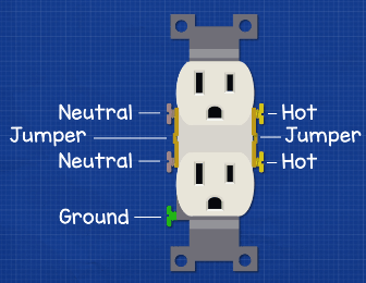
If we take a typical receptacle, we’re going to find two neutral terminals on the left which are silver in colour, and then two brass coloured hot terminals on the right, then we’ll also find a ground terminal too which is green.
Between these respective sets of terminals we have a jumper but we’ll come back to this a little later.
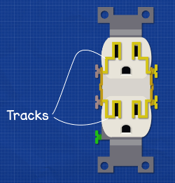
Inside the outlet we’ll find some tracks which carry the electricity. The two neutral and the two hot terminals are currently joined together by the jumper, so both hot terminals will become energised if either of the two were wired into the circuit.
We can remove the jumpers using some pliers to snap them off. These can’t be replaced though. By snapping these off we can isolate the terminals and connect them to different circuits.
Connecting Receptacle Into Electrical System
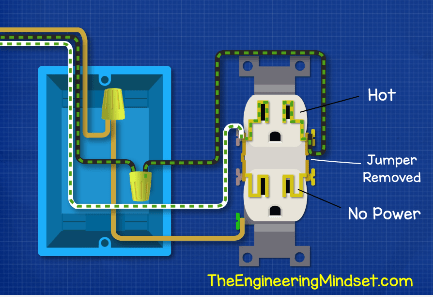
We can connect this receptacle into the electrical system by first bringing in our hot wire and connecting that to the hot terminal. Then we bring the neutral wire in and connect this to the neutral terminal on the opposite side. To make the circuit safe we bring in our ground wire also.

If we now turn on the power, the electricity will flow along the hot wire and into both the tracks for the hot terminals. The electricity wants to reach the neutral terminals to return back to the service panel but it can’t at the moment because there is no path to complete the circuit.
As mentioned, with the jumper in place, both hot terminals are now hot. However, if we remove the jumper between these two then only the terminal connected to the hot wire will be energised, in this case that’s the top outlet.
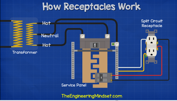
To complete the circuit we need to plug something into the receptacle. For example, we can plug in a simple light fitting. With the light plugged in, the electricity can now flow through the hot terminal and into the plug, it will then flow along the cable and into the lamp. From there it will return to the neutral terminal of the outlet and then return to the service panel and off the transformer outside, where its circuit completes.
With the jumper in place, the lamp will also light up if we plugged it into the lower plug socket. But when we remove this jumper, the circuit is broken and the lower hot terminal, in this example, is no longer hot and will not power the lamp. With the jumper still removed we can still plug the lamp into the top circuit to complete the circuit and power the lamp.
Why Would We Want To Remove The Jumper?
One application is when using switched receptacles like this circuit above which allows one half of the receptacle to remain hot while the other half is controlled by a switch.
For this we bring the hot wire in and connect to the wire nut, then we run another hot wire from there and over to the top hot terminal. We can then run our neutral wire back to the service panel. Of course, we need to also include our ground wires too.
If we powered this circuit only the top half of the circuit would be hot, the lower half would have no power. In order to connect the lower half to the switch, we run a white wire from the hot wire nut and take this over to the lower terminal of the switch. We need to place some tape on this wire to warn that is it hot.
Then, from the top terminal of the switch we run a black wire over to the lower terminal of the receptacle. Now when we power this circuit, we again get electricity to the top terminal and we have given it a second path which leads over to the switch. The switch is off currently so electricity can’t pass it.
When we flip the switch, the circuit is now made and electricity can flow over to the lower half also. If something was plugged into either; then electricity can flow through and into the neutral side to get back to the service panel. If we flip the switch off, then the power is cut again to the lower half but the top half remains hot.
Connecting To Different Hot Wires
Another application is to connect to different hot wires. If we remove the jumper and then bring in our red hot wire as well as the black hot wire, we can connect the top half and bottom half to different breakers. This will spread the electrical demand over two breakers instead of just one so it’s less likely to overload and trip the breaker.
So far the animations detail the flow of electricity using DC or direct current which flows in one direction, like the flow of water down a river. This method is used because it’s simple to visualise and understand. However, electricity in your home actually flows forwards and backwards because it is AC or alternating current. It flows like the tide of the sea, back and forth constantly. Alternating current changes direction 60 times per second. Don’t worry too much about that for now. If you want to learn how electricity works then check out our simplified tutorial HERE.
Additionally we’ve also covered split phase electricity in your home in great detail, do check that out HERE.
The Purpose Of The Ground Wire
This ground wire in the circuit is an emergency path to try and save you from an electric shock. Ideally, the ground wire in the circuit will never be used, but should a ground fault occur then the wire is on standby ready to take over.
Under normal operating conditions, the electricity will flow into our home, through the service panel and circuit breaker and then into the hot terminal of the receptacle. If we plugged something in then it could make its way over to the neutral wire and then out through the neutral incomer over to the transformer. Again, the animation details the flow of electrons in one direction for simplicity.
In the event of a ground fault, which is where the electricity took an unexpected route back to the source instead of passing through an electrical device, for example the hot wire came into direct contact with the metal casing of the switch, then the electricity will flow through the metal body and into the connected ground wire where it will continue over to either the neutral or separate ground bus bar and then up through the neutral wire and into the transformer.
As this occurs, the current in the circuit is going to increase dramatically and almost instantly. In most cases this sudden and large rise in current is detected by the circuit breaker which will trip to cut the power to the individual circuit. The electricity will continue to flow into the building and into the other circuits on the service panel. The fault will need to be corrected and the circuit breaker flipped again.
We’ve covered ground, hot and neutral wires and faults in great detail in our previous article. You can read it HERE.


")


")

")

Thanks for the lesson. This is very plain explanation. Just one thing. Can we say a receptacle is and electric extension?
Why is the ground prong receptor not explained? Why is it not connected to the actual ground wire connector?