

Learn about optocouplers. In this article we’ll look at how they are used to control circuits, how they work and also how to design some simple optocoupler circuits to show the working principle.
Scroll to the bottom to watch the YouTube tutorial.
What is an Optocoupler?
Optocouplers are integrated electronic components that look something like this.
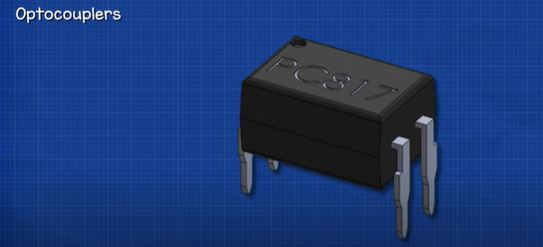
They are also known as optoisolators, optical isolators and photocouplers. In this version we have the main body with 4 pins. Pin 1 is the anode, pin 2 in the cathode, pin 3 is the collector and pin 4 is the emitter.
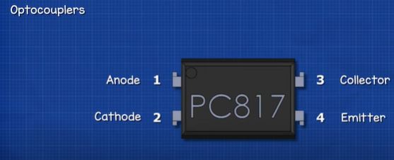
We also have a small circular indentation in the body next to pin 1, and we use this is identify the different pins. On the body we also have some text, this is the part number. We use this to identify the type of optocoupler and also find the manufactures datasheet.
This device is basically a solid-state relay which interconnects two separate circuits. Circuit one is connected across pins 1 and 2, the second circuit is connected across pins 3 and 4. This allows circuit 1 to control circuit 2. We can also use it to transfer a signal across, but the two circuits are electrically isolated from each other.
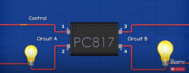
Why is that important? Because voltage spikes and noise on one circuit will not destroy or disrupt the other circuit. So, our circuits are protected. They will also only allow electrons to flow in one direction because of the semiconductor materials inside.
The two circuits can therefore use different voltages and currents because of the separation. We can expand the capabilities of the device by adding other components such as a transistor to the output of circuit two. This allows us to control even higher voltages and currents and automate circuit control.
How Does it Work?
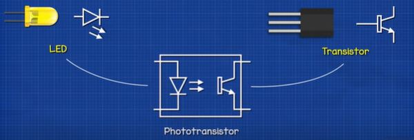
There are a few variations of optocouplers but we’re going to stick with the basic photo-transistor version for this article. When we look at the symbol of this optocoupler, we see there is an LED symbol on the left and on the right side the symbol looks very similar to a transistor, that’s because it is a modified version of a transistor known as a phototransistor. The terminals are named collector and emitter, just like a normal transistor, except we’re missing the base pin.
In a normal transistor circuit, we have the main circuit and a control circuit. The transistor is blocking the current in the main circuit so the light is off. When we apply a small voltage to the base pin, this will turn the transistor on and it will allow current to flow in the main circuit, so the main light turns on.
By the way we have covered how transistor work in detail in our previous article, click HERE.
The transistor within the optocoupler works slightly differently. It also blocks the current in the main circuit but it acts as a receiver. When the light emitted from the LED hits the transistor, this will turn it on and allow current to flow in the main circuit.
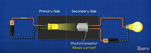
So, when circuit 1 is complete, the LED turns on. This shines a beam of light across, which hits the transistor. The transistor detects this and turns on, allowing current to flow in circuit 2. We simple control this by turning the internal LED on and off. The phototransistor acts like an insulator, blocking the flow of current, unless it’s exposed to light.
The LED and transistor are both enclosed within the case so we can’t see them, but we can see how they work with these simple circuits, which we will make later on in the article.
So how does the LED turn the transistor on? Inside the phototransistor we have different layers of semiconductor materials. There are N type and P type, which are sandwiched together. The N type and P type are both made of silicon, but they have each been mixed with other materials to change their electrical properties. The N type has been mixed with a material which gives it lots of extra as well as unneeded electrons. These are free to move around to other atoms. The P type has been mixed with another material which has fewer electrons. So, this has lots of empty space where electrons can move to.
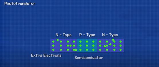
When the materials are joined together, an electrical barrier develops and prevents the electrons from flowing. However, when the LED is turned on, It will emit another particle known as a photon. The photos hit the P type material and knocks the electrons across the barrier and into the N type material. The electrons at the first barrier will now also be able to make the jump and so a current is developed. Once the LED is turned off, the photons stop knocking the electrons across the barrier and so the current in the secondary side stops.
So, we can control a secondary circuit just be using a beam of light.
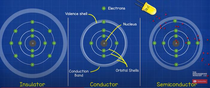
This works because of the semiconductor material. In normal wires the copper is the conductor and the rubber is the insulator. Electrons can easily flow through the copper but they can’ flow through the rubber insulator. Looking at the basic model of a metal conductor, we have the nucleus at the centre with is surrounded by a number of orbital shells which hold the electrons. Each shell holds a maximum number of electrons and an electron needs a certain amount of energy to be accepted into each shell, those furthest away from the nucleus have the most energy.
The outermost shell is known as the valance shell, a conductor has between 1 and 3 electrons in its valance shell. The electrons are held in place by the nucleus, but there is another shell known as the conduction band. If an electron can reach this conduction band, then it can break free from the atom and move to other atoms.
With a metal atom, such as copper, the valance shell and the conduction band overlap, so it’s very easy for an electron to break free and move to another atom. With an insulator, the outermost shell is packed, there’s very little to no room for an electron to join. The nucleus has a tight grip on the electrons and the conduction band is far away so the electrons can’t reach this to escape. Therefore electricity can not flow through this material. However, a semiconductor is different, it has one too many electrons in its valance shell for it to be a conductor, so it acts like an insulator. But, the conduction band is quite close, so if we provide the electrons with some external energy, some electrons will gain enough energy to make the jump into the conduction band and become free. Therefore, a semiconductor can act as both an insulator and a conductor.
Circuit 1 LED and LDR
The first circuit we will look at uses a light dependant resistor and a white LED. The LDR varies its resistance depending on how much light it is exposed to. In darkness it has a very high resistance, in bright light it has very low resistance.
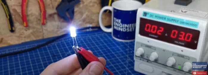
This white LED is rated for 20mA, if I connect this to the DC bench power supply, we see it requires 3V to achieve the 20mA.
When I test this LDR, we see that with a dim light it’s around 40 kiloohm resistance. When I hide it in my hand it’s around 4 megaohm and with two hands completely covering it, it’s around 9 megaohms. But, when I shine the white LED onto the LDR, its around 66 ohms. If I wrap my fingers around them, it’s around 70 ohms.
So, on the primary circuit we need a white LED which has a voltage drop of 3V and uses 0.02A of current. We will control this with a switch and use a 9V battery to power the circuit. The resistor is found by 9V subtract 3V for the LED, equals 6V. This will be the voltage drop of the resistor. The circuit current is 0.02A so 6V divided by 0.02A is 300 ohms.
Now, it will work fine at 0.02A but I’m going to use a slightly higher resistor value to reduce the current of the LED, this will also slightly reduce the brightness of the LED. I’m going to use a 330 Ohm and a 22Ω Ohm resistor which combines to form 352 ohms of resistance. 6V divided by 352 ohms is 0.017A.
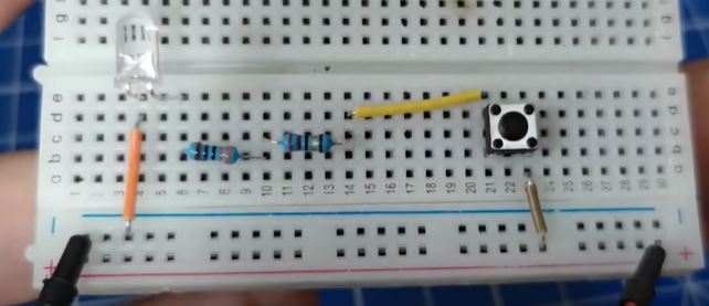
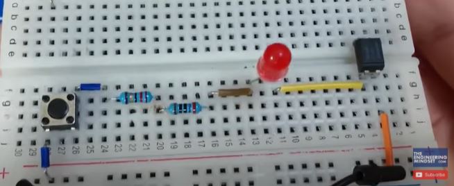
I place the components into the circuit and it looks like this. The current will flow through the circuit like this, shown using conventional current. When I press the switch the LED illuminates.
On the secondary side, we have a red LED with a voltage drop of 2V and a current of 0.02A, this will turn on to indicate the circuit is working. We place the LDR opposite the white LED, this will provide a resistance of approximately 70Ω ohms when exposed to light. To find the resistor for the LED we simply need to do 9V subtract 2V which is 7V. 7V divided by 0.02A is 350 ohms. 350 subtract 70 ohms for the LDR is 280 Ohms. Instead of this, I’m going to use two 150 ohm resistors which equals 300 ohms. So, assuming the LDR is 70 ohms, we have 370 ohms of resistance. 7V divided by 370 ohms is 0.019A.
So, I place the components on the secondary side of the circuit and it looks like this. Notice the red LED is on, that’s because the LDR is receiving ambient light from the room. If you take some electrical tape, cut off a few small pieces and wrap them around both the LDR and the LED.
This blocks the ambient light of the room and the LED is now off. When I press the button on the primary circuit, the white LED turns on, this shines the light on the LDR which turns the red LED in the secondary side on.
Circuit 2 – Infrared Emitter and Receiver
The problem with circuit 1 was that natural light activated the circuit. So, we will use an infrared emitter and receiver instead, for this circuit.
On the primary side we have an infrared emitter, the one I’m using is rated for 30mA but I’m going to use less current than this. When I test the LED we see at 1.2V it has a current of 0.02A. So, we will use this value. By the way, if you look at this with your eye you wont see any light because it’s infrared and humans can’t see infrared, so you’ll assume it’s off but it’s not. If you use the camera of your phone, you’ll see it is actually on. You can test this yourself using your TV remote as it also uses infrared.
So, on the primary side we have a 9V supply, and an infrared LED emitter with a voltage drop of 1.2V. We place a red LED into the circuit to indicate when the circuit is activated, simply because we can’t see infrared. This has a voltage drop of 2V and a current demand of 0.02A, so 9v subtract 2V subtract 1.2V is 5.8V. The current of the circuit will be 0.02A so 5.8V ÷divided by 0.02A is 290Ω Ohms. I don’t have a 290 ohm resistor so I’m going to use a 270 and a 22 ohms resistor. This gives 292 Ohms. 5.8V divided by 292 Ohms is 0.01986A so that is fine. We will also use a switch to control this.
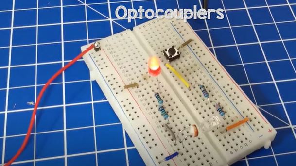
When I connect the components into the circuit it looks like this. When I press the switch, the red LED turns on and the infrared LED emits a beam of light.
On the secondary side, we have the receiver LED, this one is rated for up to 1.4V and 30mA. We will include a red led on this side to indicate when the circuit is activated. This has a voltage drop of 2V and has a current of 0.02A. So, we have 9v on the supply, subtract 2V, subtract 1.4V is 5.6V. 5.6 divided by 0.02A is 280 ohms. I will use a 270 ohm and a 10 ohm to get the required 280 ohms.
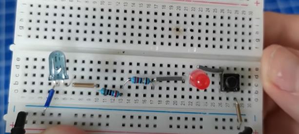
I place these components into the circuit and it looks like this. The emitter and receiver are opposite and in close proximity. When I press the switch, the primary red led turns on and the emitter shines a beam of infrared light at the receiver. The receiver detects this and allows current to flow so the secondary side red led also turns on.
Circuit 3 Optocoupler Circuit.
The third circuit uses a PC817 optocoupler.
The input side uses an internal LED, the LED is rated for 1.2V and 20mA. I can connect one to the DC power supply and see at 1.2V the current is 0.02A so we will use this value. On the input side we will use a switch to control the circuit and a red LED to indicate when the circuit is activated. This has a voltage drop of 2V and a current of 0.02A. So with a 9V supply, 9V subtract 2V, subtract 1.2V is 5.8V. 5.8V divided by 0.02A is 290 ohms. I’m going to use a 270 ohm and a 22 ohm resistor to make 292 ohms. 5.8V divided by 292 ohms is 0.01986A so this is fine.
I place the components into the circuit board and it looks like this. When I press the switch the red LED will turn on.
For the secondary side, the optocoupler is rated for a maximum of 50mA of current. We’re just going to use a red led on the secondary side which has a voltage drop of 2V and a current of 0.02A. The secondary side will have a 9V supply with the positive connected to the collector and the emitter connected to the negative. We must use a resistor otherwise the optocoupler will be destroyed.
Looking at the manufactures datasheet we see a chart with collector current v’s collector emitter voltage. The collector current is 20mA from our red LED. So reading the chart we move across until we hit the 20ma line, this shows the collector emitter voltage is 2V.
We have a 9V supply, so 9V subtract 2V for the LED and 2V for the transistor collector emitter, equals 5V. 5V divided by the collector current of 0.02A is 250 ohms. I don’t have a 250 ohm resistor so I will use a 100 ohm and a 150 ohm resistor, which combines to form 250 ohms.

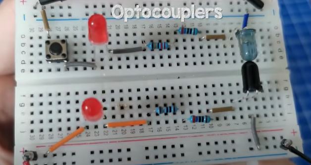
So I place the components into the circuit and they look like this. The secondary side is off, but, when I press the switch, the primary side red led turns on, the led inside the optocoupler turns on and the beam of light hits the internal phototransistor, which allows current to flow in the secondary side so the secondary red led is now on.


")

")
