

Electrical current. In this article we’re going to be discussing electrical current, we’ll be looking at what is current, the different types, how to check the ratings of your electrical devices as well as how we use safety features to save you from being electrocuted.
Scroll to the bottom to watch the YouTube video tutorial on Electrical Current
Current is the flow of electrons in a circuit. To use electricity, we need electrons to flow in the same direction around a circuit. We usually use copper cables to form the circuit because the atoms that make copper have a loosely bound electron in their outer most or valance shell which is free to move around inside the metal. This free electron is very easy to move which is why copper is so popular. It’s so easy to move that it will naturally just move to other copper atoms by its self but this occurs randomly in any and all directions which isn’t useful for us.
For us to make use of this we need lots of electrons to flow in the same direction along a circuit, we can then place things, such as lamps, in the way of these electrons so that they flow through it and generate light and heat etc.

To do this we need to force the electrons to move and we can do that by applying a voltage. Voltage is the pushing force, it’s like pressure in a water pipe, the more pressure we have the more water can flow, the more voltage we have the more electrons can flow. We’ve covered the basics of voltage in detail in our previous electrical tutorial.
So we need a lot of electrons to flow along a circuit and through our lamps to get them to shine brightly, however, the cables and lamp can only handle a certain amount of electrons passing through them, just like a pipe is rated to handle a certain amount of water passing through it or a certain pressure. If it exceeds this then the pipe will burst. Likewise if too many electrons pass through the cable or lamp then they will burst or burn out.

We refer to the flow of electrons as current and we measure this in the unit of ampere’s although you’ll usually hear people just say amps, this is represented with a capital A, for example the fuse above has a 3 and a capital A which means it’s rated for 3 Amps of current. We’ll look at how we use fuses later.
If you look on the plugs of your electrical devices you should find labels from the manufacturers which tell you what the product is designed to handle.
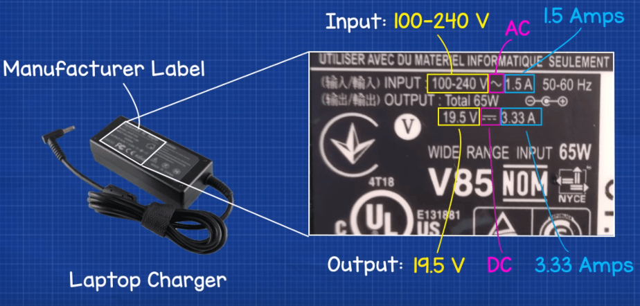
For example the laptop charger above tells us that for the device to work it needs an input of between 100 and 240 Volts and 1.5 Amps of AC or alternating current. The charger will then convert this to give an output of 19.5 Volts and 3.33 Amps of DC or direct current. AC and DC are different types of electricity. The plugs in your homes provide AC or alternating current. In this type, the electrons do not flow in a continuous loop they instead alternate between moving backwards and forwards just like the tide of the sea. Your electrical devices like laptops and mobile phones will use DC electricity or direct current. In this type the electrons do flow in one direction only, much like the flow of water in a river.
We transport electricity from the power stations in AC alternating current and send this to our cities and homes, we use AC here because it can be transported very efficiently and over much greater distances than if we were to use DC direct current. We can also very easily increase or decrease the voltage using simple transformers. We’ve covered how transformers work previously, click here to see that.
We mostly use DC direct current for the circuit boards of small electronic devices like laptops, mobile phones and TV’s. That’s because DC is easier to control and allows circuits to be smaller and more compact. Many appliances will use a combination of AC and DC. For example a washing machine will use AC for the induction motor which is used to spin the tub with the clothes in. But the circuit board which controls the settings, the lights, timers as well as how fast the motor spins will use DC power.
We can convert AC to DC using an inverter, this is extremely common in electronics. We’ve covered how inverters work previously, click here to see that.
People often refer to a river or the tide of a sea as having a strong current. It’s very similar to electricity. A river with a lot of fast flowing water is said to have a strong current, the same with electricity, a cable with a lot of electrons flowing also has a high current. A river is able to handle a certain amount of water flowing through it but if more water enters than it can handle then the river will burst it’s banks. The same with electricity the cable will burst and burn out.
Therefore manufacturers need to be able to test cables and lamps to find out how much current they can handle. We also want to be able to see how much current is flowing through our circuits as well as being able to calculate this.
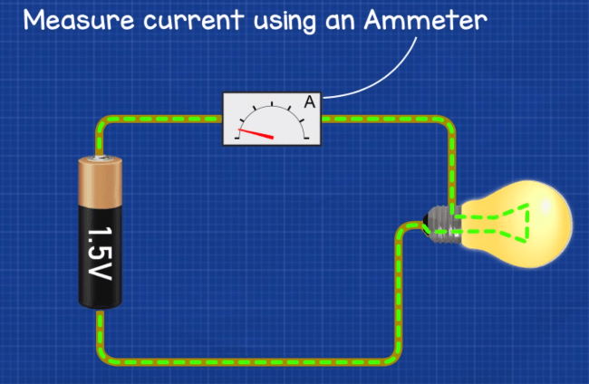
We can measure current using an ammeter and we measure the flow of current in the units of amps. So what is an amp?
One amp is equal to one coulomb, and one coulomb is equal to approximately six quintillion, two hundred and forty two quadrillion electrons per second. 6,424,000,000,000,000,000 or 6.24×10^18
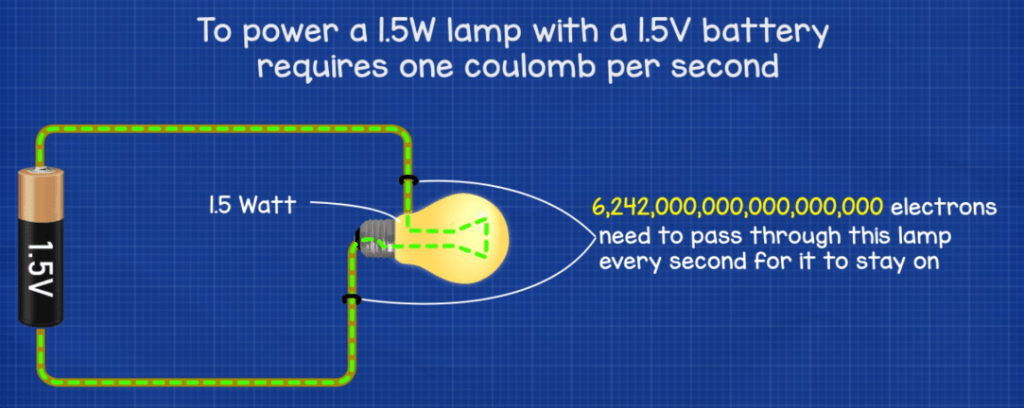
What does that mean? Another way to look at it is that to power a 1.5 Watt lamp with a 1.5V battery, approximately six quintillion, two hundred and forty two quadrillion electrons need to flow from the battery and through the lamp every second for the lamp to stay on.
If we reduce the voltage then less electrons will move and so the lamp will become dimmer. If we increase the voltage then more electrons will flow and eventually the lamp will not be able to cope so it will burst or burn out.
So to measure the current in a circuit, we need to connect an ammeter in series so that the current flows through it. Think of it like a water meter, the water needs to flow through the water meter for us to know how much water is flowing. Likewise we need the electrons to flow through our ammeter so that we know how much electricity is flowing in our circuit.
Instead of using an ammeter we’re going to use a multimeter as we can do a lot more with this device.

If you don’t already have a multimeter then I highly encourage you to get one, you can find various ones by clicking here.
If we connect a lamp to a battery in series then we can measure the current using the multimeter by connecting it in series.
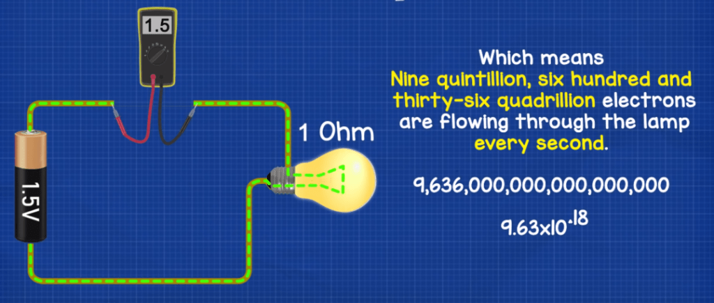
If we connect a 1.5V battery to a lamp which has a resistance of 1 ohm, then we get a current reading of 1.5Amps. Which means nine quintillion, six hundred and thirty-six quadrillion electrons are flowing through the lamp every second. 9636000000000000000, 9.63*10^18.
Because it’s in series, all the electrons in the circuit are flowing along the same path. So that means we can move the multimeter to anywhere in the circuit and we will get the same reading.
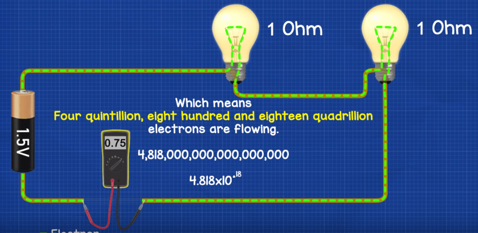
If we add another lamp to the circuit, connected again in series, the lamp also has a resistance of 1 ohm, then we’re adding more resistance to the circuit so the electrons are slowed down. In this case we get a reading of 0.75A which means four quintillion, eight hundred and eighteen quadrillion electrons are flowing. 4818000000000000000, 4.818×10^18. This is in series so again we can move the multimeter and get the same reading.
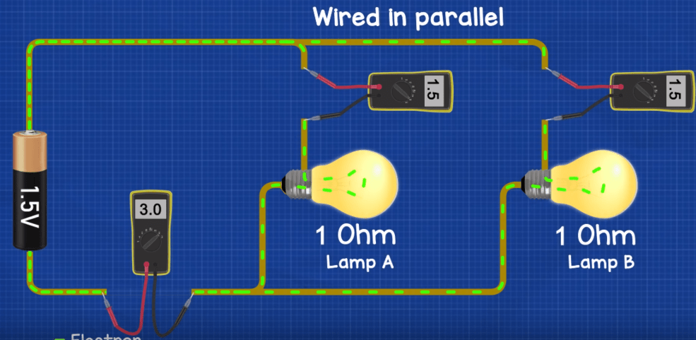
If we now connect the circuit with two lamps in parallel, both with a resistance of 1 ohm, and connect it to a battery of 1.5V, then in the main wire from and to the battery we get 3Amps, but on the branch of each lamp we get 1.5A because the path for the electrons has split so the electrons are shared with some flowing through lamp “A” and some flowing through lamp “B”. In this example both lamps have an equal resistance so the current is split equally. But if the lamps are of different resistance then the current is split unequally.
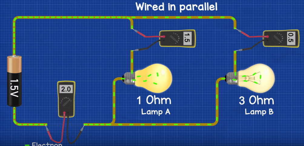
For example if lamp “A” has a resistance of 1 ohm and lamp “B” has a resistance of 3 ohm, then in the main wire we get an amp reading of 2amp, in the branch for lamp A we get 1.5A and in the branch for lamp B we get 0.5A. As you can see lamp B is dimmer because there is a higher resistance so less electrons can flow through it. In both cases the amps in the branches all add up and are equal to the total current flowing in the main wire to and from the battery.
Now I mentioned that lamp B was dimmer because the resistance was higher. If you remember I also said that cables and lamps are only rated to handle a certain amount of current, if it exceeds this then they can burn out.
So to restrict the amount of current that can flow, we can add resistors into the circuit or into part of the circuit. These act like speed bumps and slow the electrons down. Resistors are like putting a bend into a garden hose, the kink adds resistance to the flow of water which reduces the amount of water that flows out of the hose. Similarly we add resistors to the circuit and it slows down the electrons.
For example an LED is rated at 25milliAmp and 3.3V, our battery is rated at 9V, so if we were to connect the LED to the battery it will just burn out because it can’t handle that much voltage and current.
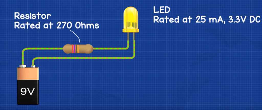
So, to stop the battery from burning out we need to place a resistor into the circuit. In this case we’ll use a 270 Ohm resistor to bring the voltage and current down to a safe level for the LED.

If you want to see how much current is flowing through your electrical devices at home, then you can use one of these cheap energy meters. You simply plug your appliances into it, and it’ll measure the voltage, amps, watts, power factor etc and you can then even calculate how much it costs to use the appliance.
So we saw earlier that we can uses resistors to reduce the amount of current flowing in a circuit and protect our devices. Another thing we can use is a fuse.
Fuses in a basic sense have a thin piece of wire inside them which is rated to handle a certain amount of current flowing through them. For example a 3A fuse is rated to handle 3 amps or nineteen quintillion, two hundred seventy-two quadrillion electrons per second. 19,272,000,000,000,000,000 1.93×10^19
The fuse acts as a weak point and is very cheap to replace, so if too much current flows in the circuit it will burnt out and open to break the circuit and protect the expensive electrical components. You can find these mounted on circuit boards and you can also find these built into some plugs. For example plugs in UK has a fuse built in, to protect the electrical device.
Another device we use, and you’ve probably seen these in your home, this is a circuit breaker. It’s essentially a switch that will automatically open to break the circuit if it detects too much current or too many electrons flowing through it, it’s rated to handle a certain amount of electrons flowing through it per second. If it exceeds this then it will open to break the circuit.
If for example, we slowly add more load to a circuit, then the bimetallic plate inside will detect the increase in current as it starts to exceeding the design rating, because the current will generate heat and the heat will activate the switch to cut the power. The load can be reduced and the circuit breaker reset.
Another extremely important function is if for example you touch a live component and receive an electrical shock, there will be a sudden surge in current and some circuit breakers can detect this and cut the power almost instantly to stop you being electrocuted and save your life.


")

")
Very helpful….thank you sir,
From= nepal🇳🇵🇳🇵🙏🙏🙏🙏🙏🙏🙏🙏🙏🙏🙏🙏🙏🙏🙏🙏🙏🙏🙏🙏🙏🙏🙏🙏🙏🙏🙏🙏🙏🙏
Hey, Paul, if the current can burn up the components of the circuit and resistors are used to reduce this current, why don’t you put them before the current meet the component, but after it already past through it(at least this happens in your illustrations)?
I was wondering that myself, but looking more into i see the current going into the battery will match the current coming from the battery when there is a single path. I assume that means the force of the voltage is as strong coming out as it is going in and vice versa.
“Because it’s in series, all the electrons in the circuit are flowing along the same path. So that means we can move the multimeter to anywhere in the circuit and we will get the same reading.” I think more emphasis is needed in the article since I thought the same as the both of you but the resistance lowers by resistor no matter where you place it on the line. And when lines are split in parallel, only the relative current is adjusted by the present resistors.
I was wondering that myself, but looking more into i see the current going into the battery will match the current coming from the battery when there is a single path. I assume that means the force of the voltage is as strong coming out as it is going in and vice versa.
Hi,
Shouldn’t be 228 ohms?
Sorry my mistake I forgot about resistance of LED.
Ub – battery voltage 9V
Id – diode current 0.025A
Ud- diode voltage 3.3V
Ur- resistor voltage = Ub-Ud so:
Ur = 9V – 3.3V = 5.7V
Resistance we looking for:
R= Ur:Id = 5.7V:0.025A=228 ohms
I was right at first 😉
Good learning experience through your website.
Thanks, RT. I learnt we have to subtract diode voltage from battery voltage before calcultaing resistor value. I was wondering about the voltage differences, which the article doesn’t explain.
[…] LEARN MORE HERE: https://theengineeringmindset.com/electrical-current-basics/ […]