

Learn the basics of the electric motor speed controller. In this article we learn how to design a simple PWM speed controller for a DC motor learning how current flows in the circuit and what each component does. You can even build the circuit yourself!
Scroll to the bottom to watch the YouTube tutorial.
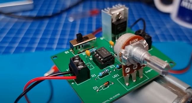
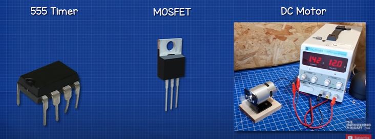
This is a simple pulse width modulation speed controller for a DC motor which uses one of these, a 555 timer, and we’re going to show you how the circuit works, how to design one and even turn it into a professional looking printed circuit board. You can even download a copy of our circuit board and build your own HERE.
Designing the Circuit
The heart of our system is the 555 timer. This is an integrated circuit component, which means inside it are a number of smaller components all combined into one package, and that makes our job as designers much easier. We’ll see how this component works as we build the circuit.
Now we’re going to be using Altium designer for this project who have kindly sponsored this article. All our viewers can get a free trial of the software HERE.
We start a new project and create our schematic and also the PCB file. We then need to start adding our components, we can use the inbuilt tool, but we’re going to use an add-on which we think makes it a little easier. We find the component on a suppliers website, We’re using mouser but you can use whoever you wish.
We’ve found the 555 timer so we take the part number and paste this into the library loader and click search, it finds the component so we click add to design.
The 555 timer can handle a maximum load of around 200 miliamps. We’re going to be controlling one of these DC motors from a 12 volt supply, and we see at 12 volt it draws a current of around 1.4 Amps and that’s with no load applied, which is already more than the 555 timer can handle. So we will need to use a MOSFET, which is a type of electronic switch.
By the way we have covered how DC motors work in detail in our previous article HERE.
We’re going to use a IRFZ24N MOSFET and that’s because it can handle both the voltage and current and it also has a low drain-source ON resistance. So we find that component and add it to the circuit. The motor will be connected to the MOSFET drain pin and the source pin connects to ground.
The MOSFET will normally block the flow of current so the motor doesn’t rotate. However, if we apply a small voltage to the gate pin, it will allow some current to flow. The higher the voltage applied, the more current is allowed to flow and so the motor rotates faster.
The 555 timer will provide the voltage to the MOSFET gate pin, from pin 3. To vary the voltage and control the speed of the motor, it will send this as pulses. Each pulse lasts a period of time, during this period there will be a segment when the signal is ON, so voltage is applied, and a segment where the signal is off, so no voltage is applied. The mosfet will therefore experience the average voltage for each time period. The wider the on pulse, the higher the average voltage will be. This is pulse width modulation and you can see the calculations for this later in the article.
The current to the gate pin is tiny, but we will place a 1 kiloOhm resistor between the mosfet gate pin and pin 3 of the 555 timer, this will protect the component by limiting the current if the mosfet were to malfunction and allow current to flow out of the gate.
A charge of electrons will build up at the mosfet gate pin and we need to discharge this to turn it off, so we place another 1 kiloOhm resister and connect this to ground which provides a discharge path.
I want to connect the motor and power supply externally from the circuit board so I will now add a terminal for the input and another for the motor connection. I also want an inbuilt switch to turn the controller on and off, so I find a suitable switch and add this too. Now we will connect the input terminal to ground and then we connect the power supply to the switch. We then connect the switch output to the motor terminal. Then connect the motor terminal to the mosfet drain pin.
The electrical motor contains coils of wire so we can consider it an inductor. When inductors are powered they store energy in their magnetic field, when the power is cut, this magnetic field collapses and the inductor pushes electrons through the circuit. This causes a very large and sudden surge in energy which can damage our circuit. So we add a fly back diode which provides a path to safely circulate and diminish the energy. For this we use a 1N4007 diode which can handle the large peak current. So we add that to the circuit.
We have covered inductors, diodes and transistors in detail in our previous articles HERE- Inductors, Diodes, Transistors.
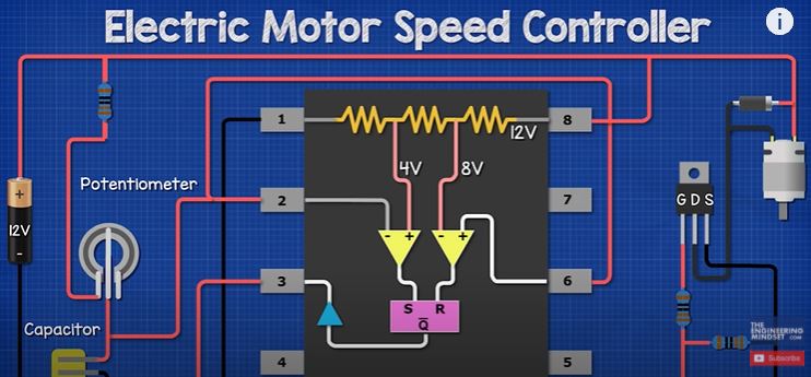
Now we can connect pin 8 of the 555 timer, which is the components power supply, and we connect this to the positive. Then we connect pin 1 to ground.
Inside the timer we have three 5 kiloOhm resistors between pin 1 and 8, the voltage reduces one third (1/3) after each resistor. As we have 12 volts at pin 8, the voltage will reduce to 8 volts after the first resistor and then down to 4 volts after the second resistor. The 555 timer uses these as a reference.
Connected to the resistors are two comparators. The comparator has a positive and negative input as well as a single output. The first comparator is connected to the resistors through the negative input. The positive input is connected to pin 6, the threshold pin. Comparator 2 is connected to the resistors via the positive input. Its negative input is connected to pin 2, the trigger pin.
The comparators are now connected across two different voltages, so it can compare them. If the positive input voltage is higher than the negative input, it outputs a high signal or positive voltage. If the negative input voltage is equal to or higher than the positive input voltage, it will output a low signal or zero voltage.
We will connect pin 2 and 6 together so that the voltage is the same. The output from the comparators connect to another internal component called the flipflop. The first comparator connects to the input called “reset”, the second comparator connects to the input named “set”. There is also an output named “not Q”. When the flipflop receives a high signal from comparator 1, it outputs a high signal. When the flipflop receives a high signal from comparator 2, it outputs a low signal. If both comparators provide a low signal, the flipflop remains unchanged and continues. This will then pass through another component called an inverter, which simply inverts the signal it is given.
If this seems confusing, don’t worry it will make sense in just a moment as we go through the circuit.
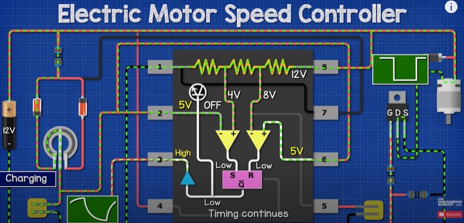
If we apply a small voltage of say 3.9Volts to pins 2 and 6, comparator 1 outputs a low signal, and comparator 2 outputs a high signal. This sets the timing interval to begin. The Flipflop outputs a Low signal. The inverter outputs a high signal.
As we increase the voltage, for example to 6 volts. Comparator 1 and 2 will output a low signal, the flipflop remains unchanged, the timing continues. But, at 8Volts, comparator 1 outputs a high signal, and comparator 2 outputs a low signal. The output of the flipflop now reverses and the output is high. This resets the timing.
The output of the flipflop remains the same until the voltage decreases to around 4 volts, where comparator 1 outputs a low signal and comparator 2 outputs a high signal, this starts the timer again.
So we see that as the voltage on pins 2 and 6 increases and decreases, the output of the 555 timer changes. So, to control the voltage and therefore the time interval, we connect pins 2 and 6 to a capacitor.
When we connect a capacitor to a power supply, it instantly reaches the battery voltage. But if we connect it via a resistor, the resistor slows down the charging time. The larger the resistor, the longer it takes to charge the voltage up.
So to charge our capacitor we will use a fixed 1 kiloohm resistor and a 100 kiloohm potentiometer. The potentiometer is a variable resistor so we can therefore vary the capacitor charging time. We will need to also discharge the capacitor in order to restart the timer. So, we will add two diodes to create a separate charge and discharge path. The current in this part of the circuit is very small since the resistors are in the kiloohm range. We will use two 1N4148 diodes, which have a forward current of around 300 miliAmps which will be fine for this application.
The capacitor will be a 10 nano farad ceramic capacitor, we will see why in just a moment. So we add these components to the circuit, then connect the diodes to the fixed resistor, and the diodes to pins 1 and 3 of the potentiometer. Then we connect the capacitor to ground as well as to pin 2 and 6 of the 555 timer and also to pin 2 of the potentiometer.
Pin 7 is the discharge pin, which is connected to our timing capacitor. Inside the 555 timer, the output of the flipflop connects to the gate pin of an internal transistor. This controls the flow of current from the capacitor to ground. When the flipflop output is low, the transistor is off, so the capacitor charges and the voltage begins to increase. When the voltage increases enough so that the output of the flipflop is high, the transistor is turned on which discharges the capacitor and so the voltage reduces. When it reaches 4Volts, the capacitor begins to charge again, when it reaches 8Volts it will discharge.
You can learn how capacitors work in our previous article HERE
We also have pin 5, which is the control voltage. We can use this to override comparator 1. We don’t need that for this circuit so we connect this to ground via a 0.1 micro farad ceramic capacitor. Grounding this pin prevents accidental override and the capacitor will filter out any noise or frequency.
We also have pin 4, the reset pin, which we will connect to the positive of the circuit. We could use this to override and reset the flipflop by interrupting the power. We don’t need that for this circuit so it is connected to the positive.
Ok, so when charging the current flows through the resistor, diode and left side of the potentiometer, to the capacitor. The flipflop output is low so the discharge transistor is off. Pin 3 outputs a high signal.
Once the capacitor charges to 8V, the flipflop output becomes high, which turns the transistor on and the capacitor discharges through the right side of the potentiometer and diode. Pin 3 outputs a low signal.
The transistor remains open so the capacitor discharges until it reaches 4V where the flipflop reverses again, turning the transistor off, which starts the timing again. This cycle repeats continuously. The capacitor charges and discharges creating a saw tooth wave and the 555 timer outputs a square wave, which is pulse width modulated.
We can calculate the performance like this.
The capacitor charges through R1 and the left side of the potentiometer. So the charge time is calculated with this formula. If we assume the potentiometer was at 50%. Then we get 0.35 miliseconds.
The capacitor discharges through the right side of the potentiometer, so the discharge time is calculated with this formula. This gives us 0.34 miliseconds.
Each cycle is the on and off time combined, so 0.35 plus 0.34 gives us 0.69 miliseconds.
The frequency is 1 divided by the cycle time, which gives us 1,428 Hertz
The duty cycle is calculated like this, so the output is on, for around 50% of the time.
We use the 10 nanofarad capacitor because it gives us a very high frequency and the DC motor works best at high frequency. If we used a very large capacitor, for example 100 mirofarads, the frequency drops to 0.14 Hertz and each cycle takes 7 seconds to complete. So, you can use other size capacitors but consider how this will impact the motors speed.
OK, so I will now build a simple prototype on a breadboard to check it all works. It seems to be fine and I can adjust the speed, so we will finish the PCB design.
We add the annotations. Then we import the components to the PCB design file and we spend some time re-arranging the components around the board. Once ready, we then outline the board, and convert this to the “keepout”. Then define the board shape. We add some text on the terminals so we know the polarity of the circuit when we go to use it. We will then use the Auto route feature to connect everything. Once it is complete, we will increase the width of the routes which will carry a higher voltage and current. An increase to 1mm should be fine. We will probably need to move some of the routes to a better location, so do check your design over. Once satisfied, we create our polygon. And then finally we can export our gerber files.
Manufacturing the PCB
So now we’re ready to have our circuit board printed.
We’re going to be using JLC PCB to print our circuit board, who have also kindly sponsored this video. They offer exceptional value with 5 circuits boards from just $2. Do check them out, I’ll leave a link in the video description for you.
Don’t forget you can download my design files, again links in the video description for that.
So, we simply login and then upload our gerber file. After a few seconds it generates a preview of the circuit on screen. We can then customise the design with different colours and materials etc. But I’ll leave these as default and save it to cart. Then we head to the checkout, fill out our postage details, and then select the postage option. I personally want this very fast so I select the express postage which is more expensive, you can choose the slower methods to save on costs. Then we submit the order and pay.
A few days later our circuit board arrives in the post. The boards look great, I’m very happy with the result.
So, we start soldering the components to the board. I start from the centre and work my way out. I’m using a holder for the 555 timer, which will stop the component from being damaged by heat and allows us to easily replace the component if faulty. With tricky components like this we can use some tape to hold in place whilst we solder it.
So we solder all the components into place, using tape wherever needed. And after a few minutes we should have a perfect looking circuit board.
Now for the test, we connect the bench power supply and motor to the board. Then turn the power supply on. I switch the board on to power it, and then, as I adjust the potentiometer the motor shaft beings to rotate. The rotational speed can be increased or decreased very easily. So we have a very basic Pulse Width Modulation DC Motor Speed controller.
Checkout one of the videos on screen now to continue learning electronics engineering and I’ll catch you there for the next lesson. Don’t forget to follow us on facebook, Instagram, linkedin as well as the engineering mindset.com


")

")

The gerber file isn’t accessible through the shared link. I would ask the admin to check out this issue and make the required changes.