In this article, we’ll explain what a diode is and how it works.
Scroll to the bottom to watch the YouTube tutorial.
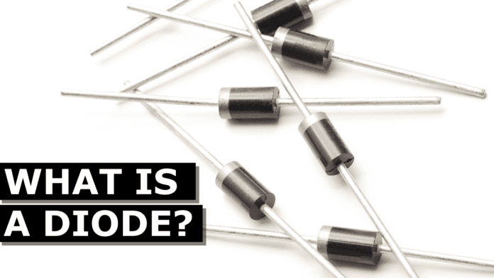
A diode looks something like this and it comes in different sizes. They typically have a black cylindrical body that has a stripe at one end as well as some leads coming to allow us to connect it into a circuit. This end is known as the anode and this end is the cathode, but we’re going to see what that means later on in this article.
You can also get other forms such as the Zener diode or an LED which is a light emitting diode but we’re not going to cover those in this article.
A diode allows current to flow in only one direction in a circuit, if we imagine a water pipe with a swing valve installed as water flows though the pipe, it will push open the swing gate and continue to flow through. Hwever, if the water changes direction the water will push the gate shut and this will prevent it from flowing. Therefore water can only flow in one direction.
This is very similar to a diode we use them to control the direction of current in a circuit, now I’ve animated this video using electron flow which the electrons flow from the negative to the positive. However you might be used to seeing conventional flow which is traditional in electronics engineering and this is where the electrons flow from the positive to the negative. Electron flow is what’s actually occurring but you might come across conventional currents still as these explanations are easier to understand. Just to be aware of the two and which one we’re using.
So if we connect a diode into a simple LED circuit like this one, we see that the LED will only turn on when the diode is installed the correct way and that because it allows current to flow in only one direction. So depending on which way the diode is installed this will act as either a conductor or an insulator. In order for the dye to act as a conductor, the stripe end is connected to the negative and the black end is connected to the positive. This allows current to flow. We call this the forward bias.
if we flip the diode, it will act as an indicator and the current can’t flow, and we call this the reverse bias. As mentioned, we use diodes to control the direction of current flow in a circuit. That’s useful for example to protect our circuit if the power supply was connected back to front. A diode can block the current and keep our components safe. We can also use them to convert alternating current into direct current. As you might know AC or alternating current moves electrons forwards and backwards creating a sine wave with a positive and a negative half. But DC or direct current moves electrons in just one direction which gives us a flat line in the positive region. If we connect the primary side of a transformer to an AC supply, and then connect the secondary side to a single diode, the diode would only allow half the wave to pass and it would block the current in the opposite direction. So the secondary side of the circuit experiences only the positive half of the cycle so its therefore now a very rough DC circuit. Although the current pulsates. But we can improve this.
One way to do that is if we connected 4 diodes to the secondary side. We create a full wave rectifier. The diode controls which path the alternating current can flow along by blocking or allowing it to pass.
As we just saw the diodes the positive half of the sine wave to pass, but this time the negative half is also allowed to pass. Although this has now been inverted to turn it into a positive half also.
This gives us a better DC supply because the pulsating has greatly reduced. But we can still improve this further. We simply add in some capacitors to smooth out the ripple and eventually get it to a smooth line closely mimicking a DC supply.
We’ve covered how capacitors work in great detail in our previous article, check that out HERE.

