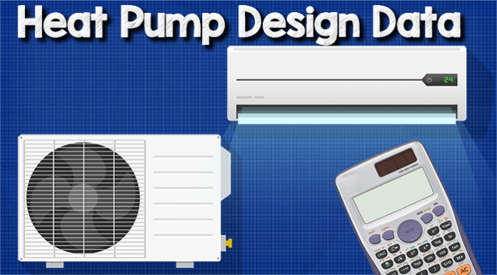
Heat pump design data. Previously we looked at how heat pumps work, but in this article we’re going to take a much deeper look and analyse some heat pump design data. We’re going to be looking at how the pressure, temperature, enthalpy, and entropy changes throughout the system as the refrigerant passes around between the main components being the compressor, the condenser, the expansion valve and the evaporator.
Scroll to the bottom to watch the YouTube tutorial on Heat Pump Design Data
I just want to point out that the numbers shown in this tutorial are used purely as an example, to help you understand what’s happening throughout the system. You shouldn’t compare these figures against an actual heat pump system. Instead, you should check with the manufacturer specifically for your heat pump model and ask them and compare it against their design data.

Heat pumps can operate in two mode, either in heating or cooling. The evaporator and the condenser will reverse roles during the change over between modes. Notice how in the heating mode, the evaporator is on the outside whereas the condenser is on the inside, and in cooling mode the condenser is on the outside and the evaporator is on the inside.
Above you can see a schematic representation of this circuit. In both circumstances, the refrigerant is passing from the compressor, into the condenser, then the expansion valve and then the evaporator before coming back to the compressor. The direction is change by making use of a reversing valve.
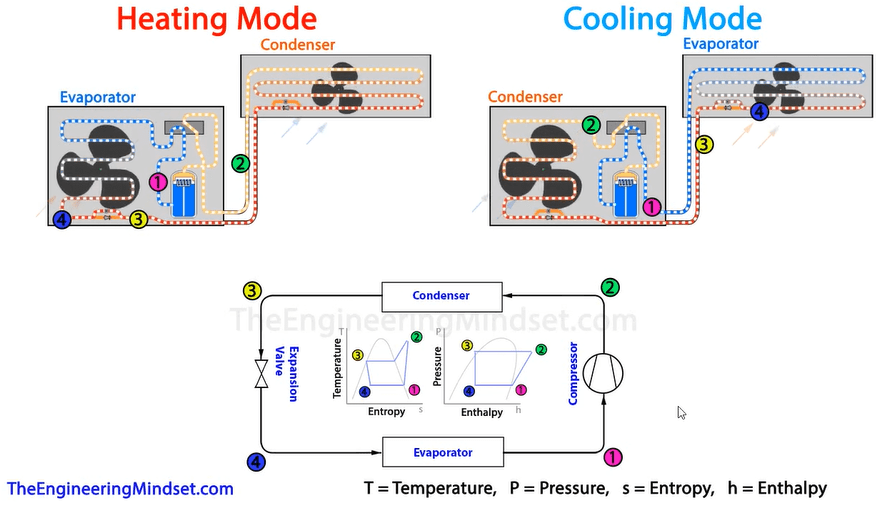
We can plot this cycle using two charts, a temperature enthalpy and a pressure enthalpy chart. Above there is a simplified version of that profile. You can notice the different points, which are different colours and number, and these correlate to a specific point in the system depending on whether the system is operating in heating or cooling mode.
Point one, is after the evaporator so the refrigerant will be a low pressure, low temperature saturated vapor as it has just picked-up the thermal energy and expanded.
Point two, is after the compressor so we know the refrigerant is going to be a high pressure, high temperature, super heated vapor.
Point three, this is just after the condenser where the refrigerant has given away it’s thermal energy and started to condense into a liquid. This is therefore going to be a high pressure, medium temperature saturated liquid.
Point four, this is just after the expansion valve and before the evaporator. We know this is now going to be a low pressure, low temperature liquid vapour mix. From here the refrigerant flows back to point one.
Heat pump example
We start at Point one. As we know, point one is a low pressure, low temperature saturated vapour. We’ll start off with a temperature of about 2.5 degrees Celsius (36 degrees Fahrenheit). It’ll have a pressure of 260 kilo pascals -260 kPa (2.6 bar).
The entropy is 0.9 kilojoules per kilogram per Kelvin – 0.9kJ/kj/K (0.45 BTU’s per pound per Fahrenheit – 0.45 BTU/lb/F). The enthalpy is going to be 246 kilojoules per kilogram – 246kJ/kg (105 BTUs per pound – 105 BTU/lb).
Now point two, we can see from the charts that it’s going to increase in temperature and pressure. There’s also going to be some increase in enthalpy as well. These increase because the compressor is doing work on the system, it’s compressing the energy into a smaller package. The pressure has raised to 1,600 kPa (16 bar). That results in the temperature increasing ti of 63 degrees Celsius (149 degrees Fahrenheit). The entropy is going to remain roughly the same, but he enthalpy will have increased as well, so that’s now 282 kJ/kg (121 BTU/lb).
At point three, there’s going to be some reduction in heat and also the pressure will drop because of the resistance from the pipework and fittings which affects flow of refrigerant. As the pressure drops and you can see there’s going to be a drop in entropy and enthalpy, so it dropped to 56°C, (133°F). There’s been a small reduction in pressure to 1,550 kPa (15.5 Bar). The entropy has also reduced. It’s almost halved to 0.46 kJ/kg/K (0.11 BTUs/lb/F). Then the enthalpy has also dropped to 134 kJ/kg (57 BTU’s/lb).
At point four, you can see from the chart there’s been a big drop in both pressure and temperature. That’s because of the expansion valve. The entropy increased slightly. That’s because the gas has been expanded, it was a liquid state before the expansion valve and now it’s a liquid vapour mixture. When it expands, the entropy increases, but notice there is no change in enthalpy or there will be very little. The refrigerant has reduced in temperature to -1.23°C (29°F). The pressure has dropped down to 280 kPa (2.8 Bar), the entropy has increased to 0.55 kJ/kg/K (0.13 BTU/lb/F) and the enthalpy as remained the same, at 134 kg/kg (57 BTU/lb).
The refrigerant will then make its way from point four back to point one, passing through the evaporator. This will lead to some increase in temperature. There is also a slight pressure drop due to fittings and pipework. As the refrigerant has picked up thermal energy here, both the entropy and enthalpy increase back to their value at point one.
The numbers will be a little different depending on if the unit is in heating or cooling mode, that’s because it will be taking thermal energy from the building or from the outside ambient air. These will be different with wind, sun, moisture content, heat sources etc.

