

Learn the basics of the timer delay relay and timer switches to understand the main types, how they work and where we use them.
Scroll to the bottom to watch the YouTube tutorial.
TELE Controls have kindly sponsored this article, and they are one of the leading manufacturers in the automation industry since 1963.
They offer some of the best timers on the market and guarantee to offer the most capabilities in functionalities and time ranges.
Take the time to review their time delay relay portfolio along with suitable relay bases and accessories. You can contact them at [email protected] or via LinkedIn. To find out more click HERE
What is a Time Delay Relay?
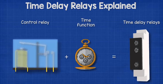
Time delay relays are simply control relays with a time delay function built in. They control an event, by energising the secondary circuit, after a certain amount of time or for a certain amount of time, some can even do both.
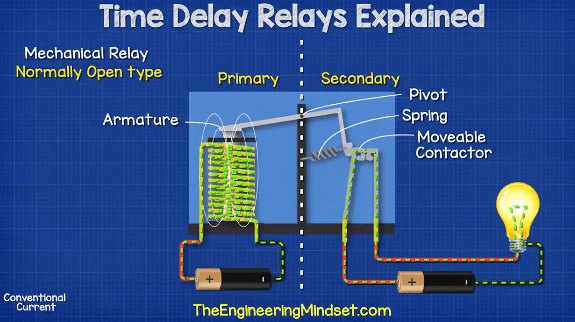
In a standard normally open control relay, the contacts on the secondary side close immediately when voltage is applied to the coil on the primary side. When the electricity is cut on the primary side, the contacts on the secondary side will open and cut the power to the load.
For some applications we do not want an immediate response on the secondary side, we want this to occur after a certain amount of time, or only for a certain duration. For this, we can use a time delay relay.
There are two main types of basic timing relays, the delay on type and the delay off type. These can be normally open or normally closed type relays and we can control the delay time from milliseconds to hours or even days.

By the way we have covered the basics of mechanical relays in detail in our previous article, do check that out HERE.
Where are Timing Relays Used
Timing Relays are used extensively in industrial applications, HVAC systems and building services to provide time-delayed switching. For example to start a motor, control an electrical load, or simply automate an action. They play a vital role for targeted logic needs.
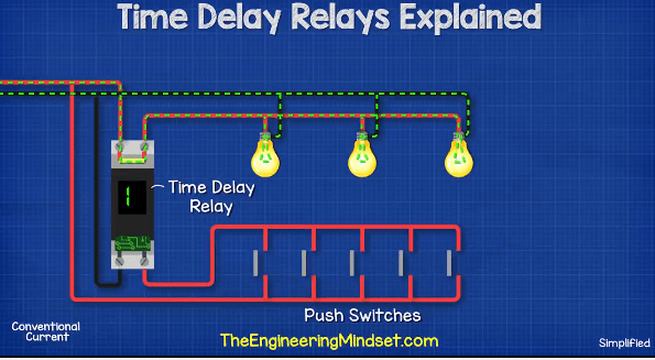
A common example you have probably seen is in a corridor or stairwell which is infrequently used. Perhaps in a place of work, or an apartment block. We don’t want the light to stay on constantly, we want it to automatically turn off. So once the light switch is pressed, the time delay relay keeps the light on for a certain amount of time. Once this time expires, it automatically cuts the power to the light.
Timing relays can be applied to almost any application, these are available as plug-in devices, base-mounted devices, circuit boards and even as DIN rail mounted controls.
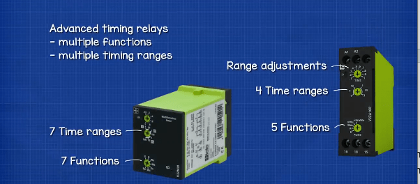
Traditionally, timing relays were available only as single-function, single-time-range devices. These devices are still available and are typically used in applications with very simple timing needs.
But we can get more advanced Timing Relays with different functions and multiple timing ranges. Most are capable ofcontrolling voltages or currents over a wide range also, so their application isn’t limited. No programming language is required to set them up, we simply adjust the settings via the dials and the manufactures guides will instruct you on how to do this.
The time delay relays and switches will operate automatically once setup and provided with a trigger or a signal to cause the action. With multi-function relays we often find an LED built into the device, this will flash at different intervals to indicate what function it is currently performing. The manufacturers guide will tell us what function the LED is indicating.
To apply a time delay relay or switch, we need to consider where will the device be installed, what will trigger the device, how long will the delay be before energising the secondary side or how long will the secondary side be energised for.
Time Delay Off Circuit
Some times we need the secondary side of a relay to remain on for a given amount of time. For example an external radiant heater which we might find at a restaurant with outdoor seating. When a customer is cold, they flip the switch. Now these use a lot of energy so we don’t want them left on for hours at a time. The customer won’t be there for too long, so we can use a timing relay. The timing relay will automatically turn the heater off, for example after maybe 30 minutes.
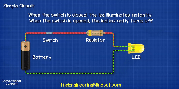
If we look at this simple circuit of a battery and an LED. When the switch in closed, the led illuminates. When the switch is opened, the led instantly turns off. How can we delay the turning off of the led?
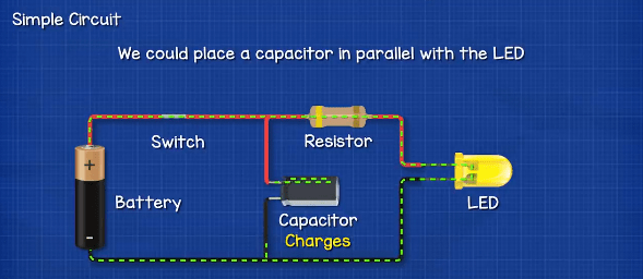
We could place a capacitor in parallel with the led. This way, when the switch is closed the LED illuminates, and the capacitor charges. When the switch is opened, the capacitor discharges and the LED remains illuminated. We can use different size capacitors to change how long the led remains powered for. We could even use a variable capacitor to allow adjustment of the time period.
The switch could be the secondary side of a relay, and uses an input signal on the primary side to start the timer on the secondary side.
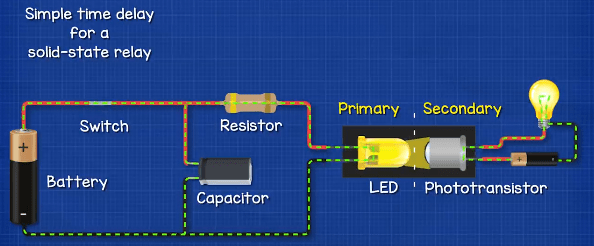
Alternatively, the LED could be on the primary side of a solid-state relay. This would therefore use the led to provide an optical coupling to a phototransistor on the secondary side.
The problem we face with this design is that the discharge rate of the capacitor is not linear so the LED slowly dims until it eventually turns off. So we might want a better design.
How can we ensure the LED remains on when the switch is opened, but also ensure it automatically tuns off if it becomes too dim.
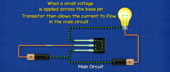
We could add a transistor to the circuit. The transistor will act something like a switch. There are different types of transistors but we won’t go into detail on those in this video. For now we will consider that the main circuit is connected across two of the transistors three pins. This type of transistor will normally block the flow of current in a circuit. But, when a certain voltage is applied to the base pin, the transistor then allows the current to flow. When the voltage to the base pin is removed, the transistor stops the flow of current in the main circuit.
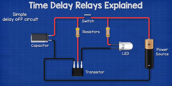
This diagram shows a simple delay timing off circuit, using a transistor, capacitor, LED and switch. The resistors are used to limit the current and protect the components.
So, we can control the current in the main circuit by sending a signal to the base pin of the transistor, this signal is a small voltage. The transistor will only allow current to flow in the main circuit, if the voltage at the base pin is at or above a certain level, typically 0.7V. If the voltage at the base pin falls below this minimum level, it will not allow current to flow.
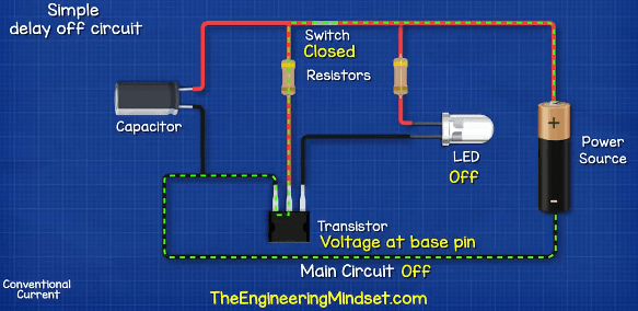
With the switch open the LED does not light up, no voltage is detected at the transistor base pin, so the transistor acts like an open switch and prevents current from flowing in the main circuit.
With the switch closed, electricity flows to the base pin of the transistor. The transistor detects the voltage and determines that it is above the minimum level, so it allow current to flow through the main circuit.
As current flows through the main circuit it illuminates the led, meanwhile the capacitor charges.
When the switch is opened, the main power supply to the transistor base pin is disconnected. The capacitor now begins to discharge and provides the voltage to the base pin. This permits the transistor to keep allowing current through the main circuit so the LED remains on.
When the voltage level of the capacitor falls below the minimum trigger value of the transistor, it will turn off, and stop the current flowing in the main circuit, so the LED turns off. The storage capacity of the capacitor therefore determines how long the circuit is powered for.
This simple design is for a time delay switch but we could again integrate this into a relay.
By the way we have covered how capacitors work in detail, in our previous article HERE
Time Delay on Circuit
Sometimes we need the secondary side of a relay to remain off for a given amount of time.
For example, when large inductive loads turn on or off, perhaps from a sudden loss of power or the start-up of a large induction motor, large voltage spikes or inrush currents can occur due to the strong magnetic flux in the circuit. These surges can damage components and equipment.
If a short delay is provided, such damage can be avoided. The time delay relay circuits are used for this purpose.

If we look at this simple delay time on circuit, the transistor is preventing the lamp from turning on. The transistor needs a minimum voltage to open and allow the lamp to turn on. When we close the switch the transistor receives this voltage and opens instantly.
How can we delay this?
We could simply connect a Zener diode to the base pin of the transistor and then connect a resistor and capacitor in parallel between the diode and the switch. Diodes only allow current to flow in one direction and block the current flowing the opposite way. However, if a Zener diode is provided a certain reverse voltage, it will open and allow current to flow in the opposite direction, this is known as the breakdown voltage. So, we can use this to control the transistor by only opening when a certain voltage is applied.
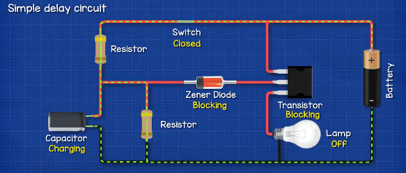
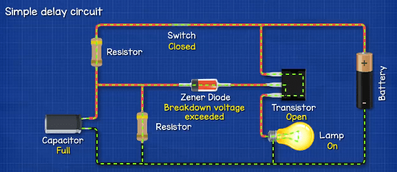
Now, when we close the switch, the current will slowly charge the capacitor. The Zener diode continues to block the current to the transistor and the lamp remains off. As the capacitor charges, the voltage increases. Eventually the voltage will exceed the Zener diodes breakdown voltage. At this moment, the diode allows current to flow through it and reach the transistor. The transistor receives this and allows current to flow through it, so the lamp turns on.
When we disconnect the switch, the capacitor continues to supply the voltage, keeping the Zener diode and transistor open. The current flows through the resistor until it drains the capacitor, once the voltage of the capacitor falls below the breakdown voltage, the Zener diode again blocks the current to the transistor and the lamp turns off.
So now, when the circuit is energised, the load will not turn on instantly. It will only turn on once the capacitor is charged to exceed the Zener diodes breakdown voltage.
This is a fairly simple design, it’s probably more common to find a IC chip inside, something like a 555 timer is used instead. But this simple design gives you a visual understanding of how a circuit might work.


")

")

Need to know what to purchase for this appliciation. I have a 24 volt zone valve, however, once the power is disconnected the zone valve closed immediately. I would like to purchase some kind of unit so that when the main power is disconnected from the zone valve, the zone valve will still be powered with 24 volts for 20 seconds then after which it closes. What do I need to purchase?
Thanks