Chiller Expansion Valve. In this article we are going to be looking at the thermal expansion valve on a chiller. We’re going to look at the three most common types of expansion valves in typical modern commercial chillers, that being the pilot operated thermal expansion valve. The thermostatic expansion valve, and also the electronic expansion valve.
Scroll to the bottom to watch the YouTube tutorial video on chiller expansion valves
The expansion valve controls how much refrigerant flows between the condenser and the evaporator. The valve responds to the suction line superheat, which is entering the compressor. It will vary the amount of refrigerant flowing into the evaporator to suit the change in cooling load. The evaporator needs a certain amount of liquid refrigerant in it for sufficient heat exchange to occur. If there’s a high amount of superheat on the suction line then there’s a lot of vapour entering the compressor. If so, then some more liquid refrigerant can be allowed to enter the evaporator from the condenser.
The expansion valve is keeping that balance between the right amount of liquid refrigerant and the right amount of superheat.
The balance needs to be right. You only want vapor entering into the compressor. If liquid refrigerant enters the compressor, it will severely damage the compressor because liquids are not compressible.
Pilot Operated Expansion Valve

Above is an image of a real world pilot operated expansion valve. The refrigerant is going to flow as a liquid from the condenser, through the while pipe, into the expansion valve and then into the evaporator. The large block attached to the bottom of the white pipe is known as a king valve. This can be used to isolate the condenser.
You will notice there is another, much smaller thermostatic expansion valve shown in the image. This feeds the pilot of the main expansion valve, the flow in this smaller expansion valve is what controls the main expansion valve. Attached to the pilot expansion valve is a capillary tube, this rides up and attaches to a thermal bulb. Which is placed on the suction line of the compressor.
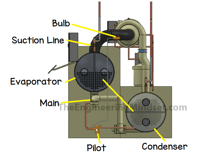
Looking at the side view of a water cooled chiller model. We can see the route of the refrigerant from the condenser into the main expansion valve and into the evaporator. The pilot valve is also connected to the condenser and feeds into the main expansion valve and it controlled by the thermal bulb on the suction line.
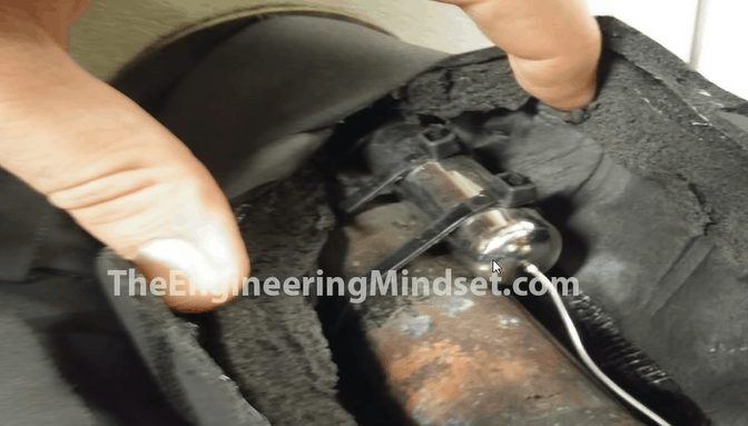
The thermal bulb will be located on the suction line, and it looks something like in the image above. A capillary tube will run between the bulb and the valve head. The bulb is filled with a refrigerant. When the superheat increases, this causes heat to transfer across, from the suction line, into the bulb.
As the bulb becomes hotter, the refrigerant inside starts to boil and expand. As that expands it pushes refrigerant out through the capillary tube and that causes a pressure increase in the capillary tube. That pressure pushes all the way along the capillary tube to the top of the pilot valve. That pressure pushes down on to the top of the valve, the pressure on the valve causes it to close or open and we use this to control the flow of refrigerant through the chiller.
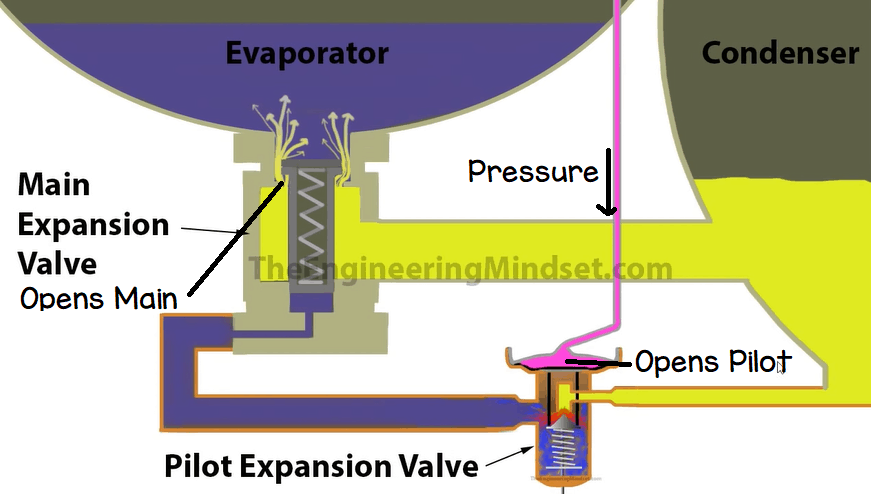
Looking at the drawing of the system. We can see that as the pressure increases in the capillary tube, the pressure will travel down and force the pilot thermostatic valve to open. The refrigerant will flow through this and lift the main expansion valve up, opening it. The refrigerant will now flow from the condenser and into the evaporator.
Thermostatic Expansion Valve
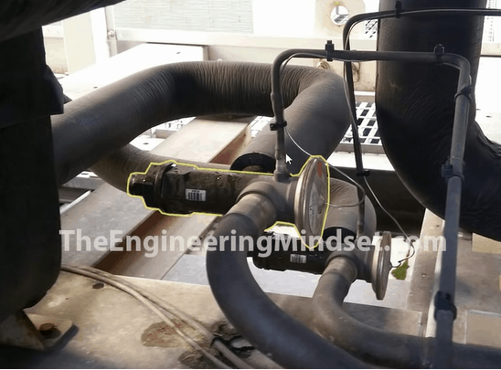
The next expansion valve we are going to look at is the thermostatic expansion valve. These are quite common on air cooled chillers which are smaller in cooling capacity. These provide the same function at the previous expansion valve, they just work a little different.
Notice on the valve there is a thin capillary tube coming off the top of the valve (the valve is on it’s side) this runs off the the suction line to measure the superheat and react to it. This particular valve also have a thicker equalisation tube coming out of the side of the valve but that’s a different subject we’ll look at at a later point.
This type is basically what we saw being used as the pilot operated valve in the previous expansion valve type, except it’s being used to directly control the chiller. There is no “main expansion valve”, it is the main valve in this design.
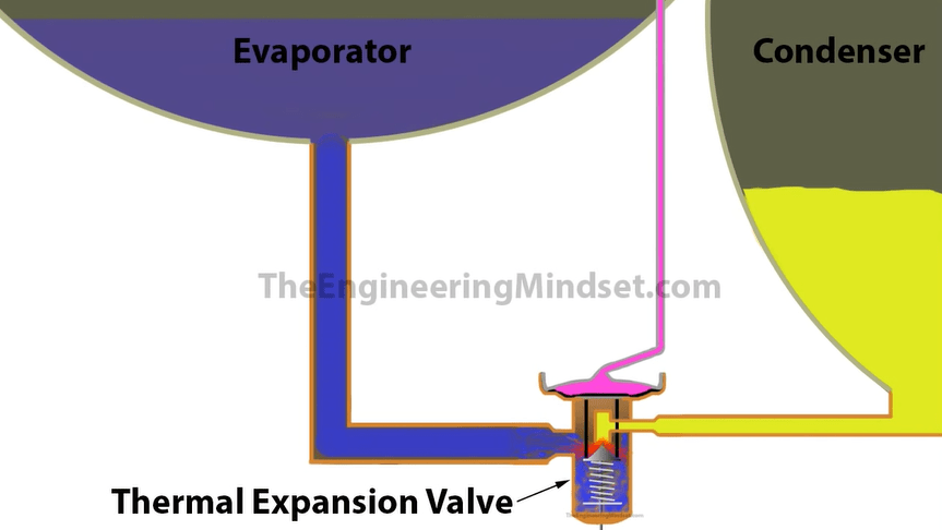
With this design we use a thermal bulb to measure the temperature of the superheat at the suction line of the chiller. As the bulb heats up the refrigerant inside boils which creates pressure in the capillary tube. The pressure travels down the capillary and pushes down on the head of the valve. As the head is pushed down, it will open the valve to allow more refrigerant to flow into the evaporator. When the superheat decreases the pressure also decreases and so the valve begins to close.
Electronic Expansion Valve
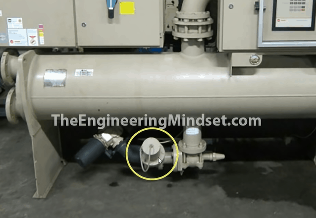
The third expansion valve we’re going to look at is the electronic expansion valve. This type of expansion valve gives the best performance because the valve uses a stepper motor in the body. The stepper motor precisely controls the positioning of the valve, allowing a very accurate and precise flow of refrigerant.
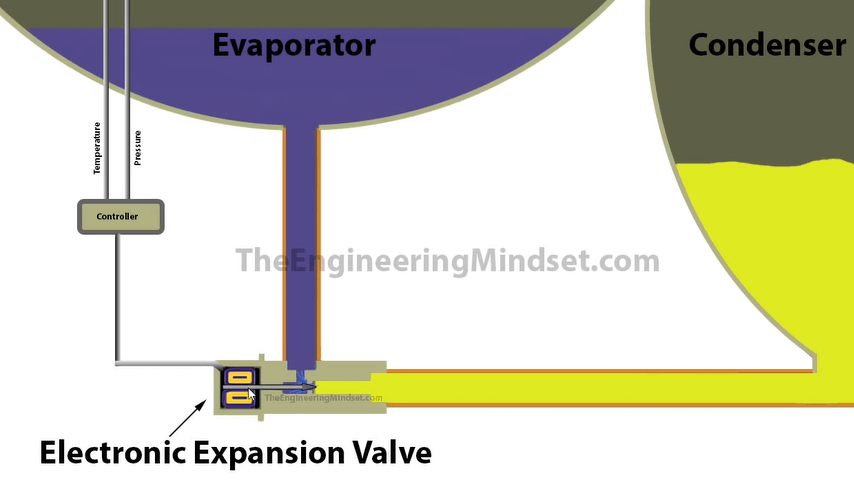
You can see in the illustration above. The stepper motor on the far left. In the centre of this is a shaft which attaches to the needle. The needle pushes against a seat in the valve. The stepper motor pushes and pulls the shaft backwards and forwards. As the shaft moves it opens or blocks the valve seat to allow or restrict the flow of refrigerant from the condenser to the evaporator. The controller measures the pressure and the temperature of the refrigerant to determine how far to open/close.

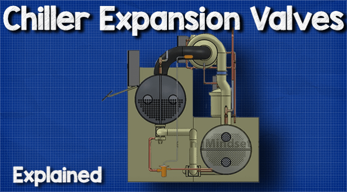






[…] The condenser which removes the unwanted heat from the system and send this to the cooling tower. The expansion valve which expands the refrigerant and controls the superheat into the compressor and the evaporator […]