

Learn the basics of the thermocouple to understand how it works as well as the different types. This article is sponsored by Danfoss.
Scroll to the bottom to watch the YouTube tutorial
What is a Thermocouple?
A typical thermocouple looks something like this.
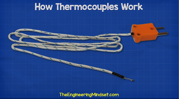
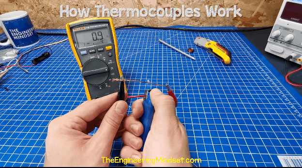
It usually comes with a hand held temperature probe or even a multi-meter. They are also built into these solid cases for a much more rugged design. Thermocouples are very quick and easy to use. By simply plugging the probe into the measurement device; in this case a cheap multi-meter – and selecting the temperature setting. We can get an accurate temperature reading in no time at all.
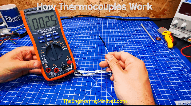
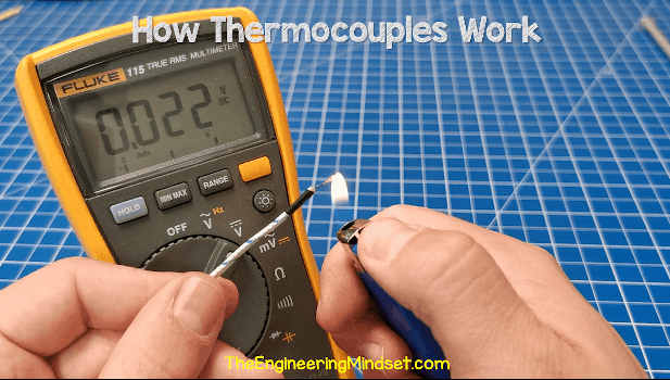
This will work for many applications. With a thermocouple we connect two different metals at one end. And the other ends connect into a terminal block. Then we use a volt meter to read the voltage difference between the two. The voltage here will be very, very small. When we connect the thermocouple to a multi-meter and then apply heat to the junction. We can see it will generate a voltage. As you can see in this example, we are able to generate a very small voltage using a flame and once we remove the heat the voltage diminishes.
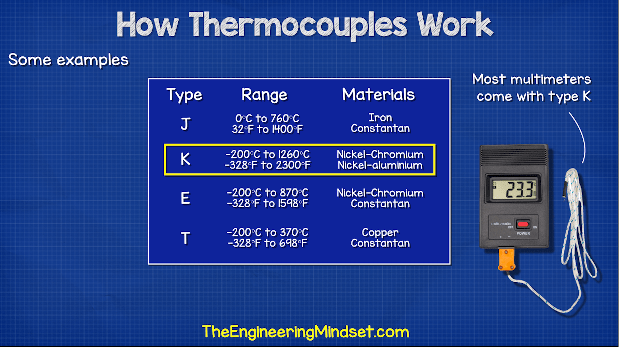
Thermocouples are available in different temperature ranges. These are shown by a letter which indicates their rated temperature range. The most common type is K. This is a very general purpose version. Each letter uses a different combination of materials. This will give us a different temperature reading and allows different temperature ranges.
How Does a Thermocouple Work?
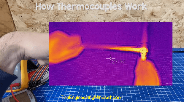
If we held a metal rod in our hand, and placed the other end into a flame. We know the rod will heat up and this heat will travel along the length of the rod to our hand. We can see this by using a thermal imaging camera. Notice the thermal energy travels along the length of the copper wire away from the heat source.
What’s happening here, is the heat is exciting the atoms and molecules which for the materials structure. The heat causes the molecules and the atoms to vibrate. This vibration is so tiny you would not be able to feel it with your hand. The excited atoms will allow their free electrons to move more easily and they will move towards the cooler end of the rod. This only occurs because there is a temperature gradient. A difference in temperature from one end to the other. So at the cooler end; we’ll have slightly more electrons than at the hotter end. As electrons are negatively charged; we therefore get a slightly negative and slightly positive charge ends of the rod.
Voltage is like pressure. When measuring the difference or potential difference; between two points. If you imagine a pressurised water pipe. We can see the pressure using a pressure gauge. The pressure reading is comparing two different points also. The pressure inside the pipe compared to the atmospheric pressure outside the pipe. When the tank is empty the gauge will read zero, because it has nothing to compare. Both are now the same in pressure. The same with voltage. We are comparing the difference from one point to another. If we read across a 1.5V battery, we can get a reading of 1.5V. But we try to measure the same side; we wouldn’t read any voltage, because there is no difference. We can only measure the difference between two different points
By the way we have also covered ‘how a battery works’ previously. Do check that out HERE.
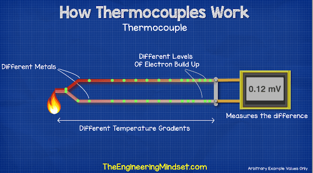
Coming back to the thermocouple. If we connected two wires together of the same material; let’s say they were both copper and we then applied heat at the end to create a temperature difference. Then the electrons would scatter and build up at the cold ends. However; they would build up in equal amounts in each wire because they are the same material. So both wires will conduct heat equally and the temperature gradient will be the same. Therefore our volt meter would not be able to measure any difference. However, if we connected two wires which were made of different materials, for example, one was made from copper and the other one was made from iron then two metals will conduct heat different so the temperature gradient will be different. That means that the electron build up at the cold ends will be different and so we can connect a volt meter to this and read a voltage difference.
To make this into a useful tool, we just calibrate it by testing the device against known temperatures and marking down the voltages generated. Then we simply use a formula to calculate the temperature from the voltage measured. For this to work best, we should submerge the cold junction into an ice bath, that way we get a voltage with a reference relative to 0 degrees Celsius. Remember I said about the pressure in a pipe and how we are comparing it to the atmospheric pressure outside. That’s because we know the pressure outside the pipe- its atmospheric pressure. So, for the voltage reading to be accurate; we need to measure against something we know, so we use ice water because we know this water is a constant zero degrees Celsius. This method is used in many science labs however as you can probably tell it isn’t very practical for most engineering applications. So instead, to improve the accuracy we leave the cold connections at equal ambient temperatures, and then we compensate for the difference by measuring the temperature of the connection and applying a formula to offset to error. To measure the temperature of the connection we often use a RTD temperature sensor, which we’ll look at next.
Resistance Temperature Detector
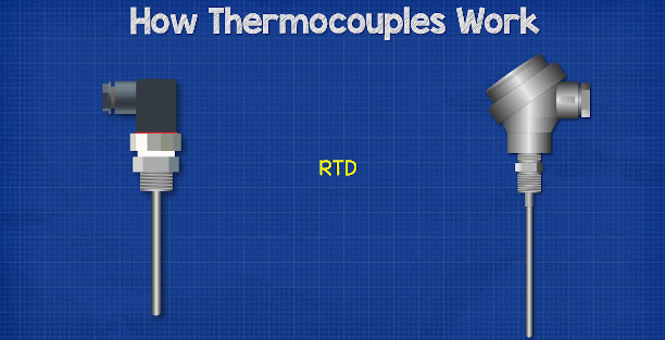
RTD stand for resistance temperature detector. This is also a fairly simple design. Its probably easier to understand than the thermocouple. They usually come in these different designs for engineering applications with rugged casing.
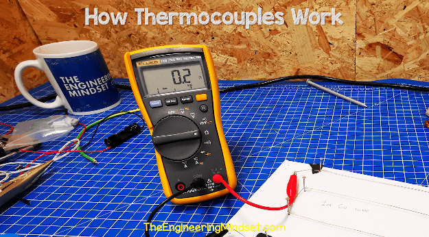
How do these work? Well we know that electricity is the flow of electrons in a circuit. When we pass electricity through a material, lets say a copper wire. The material will have some resistance to the flow of electrons. We can measure this resistance with a multi-meter. Different materials will have different resistance levels. For example, this 1m length of copper wire, shows a very low resistance of just 0.2 ohms.
But this 1m length of nickel chrome wire shows a very high resistance of 22.1 ohms.

The temperature of the material will change the resistance of the material. Most conductors will increase in resistance the hotter they get, that’s typical of metals. For example this copper wire shows a resistance of 0.1 ohms at ambient temperature but when heated with a flame it increases up to 0.9 ohms.
This occurs because as the atoms and molecules become excited they’re going to move around a lot so this makes it harder for the free electrons to get through without a collision. Using a formula known as ohms law, voltage is equal to current multiplied by resistance which means that as long as we keep the current the same, a change in resistance will cause a change in voltage. As temperature changes the resistance of a material we can measure the voltage to tell the temperature. We use a material such as platinum because it has a near linear resistance vs temperature gradient. We test the material at known temperatures to obtain the graph. For example at zero degrees Celsius the material will have a resistance of 100 ohms. And at 100 degrees Celsius it has a resistance of 138.5 ohms. There are many different designs for this type, but typically they are either a film type where the platinum is coated into a ceramic plate into a pattern and sealed in glass. Or it will be a platinum wire wound around a ceramic core again sealed in glass for protection.


")

")