Water cooled chiller design data. In this article we are going to be taking a very detailed look at the design data for a centrifugal, water cooled, chiller. This is a pretty advanced chiller video, so if you’re new to the topic then I highly recommend you start from the basics first.
Scroll to the bottom to watch the YouTube tutorial video on chiller design data.
I want to stress that this is simply design data. Every chiller is different and you should speak to your manufacturer for the relevant information. The results will vary from the real world and also with loading.
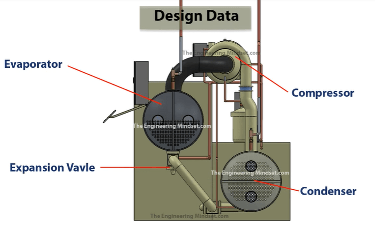
In the illustration above we have shown the main chiller components. The compressor, which is the driving force of the refrigerant around the system. The condenser which removes the unwanted heat from the system and send this to the cooling tower. The expansion valve which expands the refrigerant and controls the superheat into the compressor and the evaporator which collects the unwanted heat coming from the building and generates the chilled water.
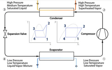
We’re going to be looking at all the points on these two charts to see the pressure, temperature, enthalpy and entropy are around this system. The left chart is our Temperature v’s Entropy chart and the right chart is our Pressure v’s Enthalpy chart.
- Point 1 is just before the compressor, and the exit of the evaporator. That will be a low pressure, low temperature saturated / slightly superheated vapor.
- Point 2 is just after the compressor, before the condenser. That’s a high pressure, high temperature superheated vapor.
- Point 3 is just after the condenser, but before the expansion valve. That’s going to be a high pressure, medium temperature saturated liquid.
- Point 4 is just after the expansion valve but before the evaporator. This will be a low pressure, low temperature and it’s going to be a mix between a liquid and vapor.
Compressor
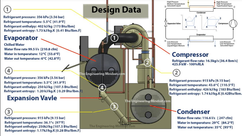
In this example the compressor is pushing a refrigerant with a flow rate of 16.5 kg/s (36.4 lbm/s). That motor is then consuming 425.9 kilowatts and the compressor is running 100% load. If the chiller runs at part load then the values will be different.
The refrigerant is being sucked in from the evaporator (Point 1) at around 356 kPa (3.56 Bar) and at a temperature of 5.5 ° C (41.9 ° F). The refrigerant enthalpy is 402 kJ/kg (173 BTUs/lbm). The entropy will be 1.73 kJ/kg.K (0.41 BTUs/lbm.F).
The compressor is compacting the refrigerant into a smaller space, and looking at our charts we know that the enthalpy is going to increase, the entropy is going to slightly increase and the pressure and temperature will massively increase.
When the refrigerant leaves (Point 2), it will be 915 kPa (9.15 bar). The temperature reaches 43.6 ° C (110.5 ° F). The enthalpy is now 426 kJ/kg.K (183 Btu/lbm) and the entropy is now 1.74 kJ/kg.K (0.042 Btu/lbm.F).
Remember the temperature of the refrigerant entering into the condenser has to be higher than the incoming condenser water temperature for heat transfer to occur. If they were the same temperature, then no heat transfer would occur and the chiller would do no cooling.
Condenser
The next part we’ll look at is the condenser. In this example the condenser water is flowing through the condenser at 116.6 L/s (247 cfm). The condenser water is coming into the condenser, from the cooling tower, at 29 ° C (84.2 ° F). The refrigerant will then transfer the buildings unwanted heat into the condenser water. This will increase the temperature of the condenser water, so when it leaves to go back to the cooling tower it will be around 35 ° C (95 ° F).
Now the reason the flow rate is higher in the condenser compares to the evaporator is because the condenser has to reject more heat. It also has to take the heat away from the compressor and other parts of the machine.
The refrigerant came from the compressor and entered the condenser at a pressure of 915 kPa (9.15 Bar), a temperature of 43.6 ° C (110.5 ° F) with an enthalpy of 426 kJ/kg.K (183 Btu/lbm) and an entropy of 1.74 kJ/kg.K (0.428 Btu/lbm.F).
Once the refrigerant has give away some of its energy to the circulating condenser water, it will now leave as a liquid at 36.1 ° C (97 ° F) but still at the same pressure as it entered. It’s entropy will have dropped to 1.17 kJ.kg.K (0.28 BTU/lbm.F) and the enthalpy increases to 250 kJ/kg.K (107.5 BTU/lbm). It then enters into the expansion valve.
Expansion Valve
The expansion valve controls the flow of refrigerant, it measures the superheat on the suction line of the chiller and then reacts to this by allowing or restricting refrigerant flow to maintain a certain value. The refrigerant is entering the expansion valve as a liquid and leaving as a vapour/liquid mixture.
It enters, in this example, at a temperature of 36.1 ° C (97 ° F), a pressure of 915 kPa (9.15 Bar), the entropy is 1.17 kJ.kg.K (0.28 BTU/lbm.F) and the enthalpy is 250 kJ/kg.K (107.5 BTU/lbm).
The refrigerant is expanded through a small orifice which sprays the refrigerant. It expands into a larger volume and decreases in pressure as a result, which allows it to drop in temperature as it’s now not packed so tightly. It will leave at a temperature of 5.5 ° C (41.9 ° F), a pressure of 356 kPa (3.56 Bar) and from the charts we know it will maintain the same enthalpy but the entropy will change slightly and it leaves at 1.20 kJ/kg.K (0.29 BTU/lbm.F).
Evaporator
The evaporator generates the cold “chilled water” which cycles around the building, providing air conditioning and collecting the buildings unwanted heat. This now warm chilled water returns to the evaporator and transfers this heat into the refrigerant, the chilled water then leaves cooler and cycles around the building, meanwhile the refrigerant boils and carry’s the thermal energy to the compressor.
In this example, the chilled water is flowing through the evaporator at around 99.5 Litres per second, which is around 210 cubic feet per minute. The chilled water enters the evaporator at around 12 ° C (53.6 ° F). After the chilled water has transferred it’s heat over to the refrigerant, it will leave the evaporator at around 6°C (42.8°F).
The refrigerant is picking up thermal energy but the temperature only changes slightly which confuses many people. The reason it doesn’t increase dramatically is because it is undergoing a phase change from a liquid to a vapour so the thermal energy is being used to break the bonds between the molecules. The enthalpy and entropy will increase and this is where the energy is going
When the refrigerant leaves it will be a slightly superheated vapour at 5.5 ° C (41.9 ° F), a pressure of 356 kPa (3.56 Bar) an entropy of 402 kJ/kg.K (173 Btu/lbm) and an enthalpy of 1.73 kJ/kg.K (0.41 btu/lbm.F).
The refrigerant then returns to the compressor to start the cycle all over again.







why the temperature after evaporator can’t cool, it is about 26 C degree,..
Hi! Which freon is now the most effective to use in the chiller?
Fantastic Paul.
Your article is full of useful information. Thank you so much for your kind article
very nice information about thermodynamics of water cooled chiller and how it works. thanks
what is the degree of superheat that you normally allow for at the compressor inlet
What is the degree of sub cooling at the inlet of the expansion valve