Centrifugal chiller compressor. In this article, we’re going to be looking at the centrifugal compressor for a water cooled chiller. We are going to be looking in detail about the operation of the compressor, it’s purpose and why it’s important.
Scroll to the bottom to watch the YouTube tutorial on Centrifugal chillers
The compressor is the driving force of the refrigerant around the system. The centrifugal compressor is mounted on the top of the chiller. It’s being fed from the suction line off the evaporator.
Lean how evaporators work here
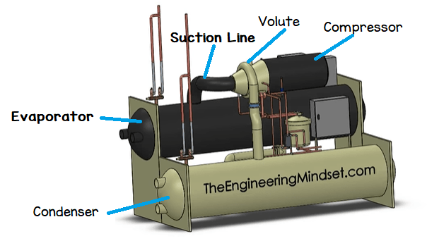
The refrigerant boils in the evaporator and is sucked into the suction line as a low pressure, slightly superheated vapour. As it enters the compressor is first passes through the vane guides. The refrigerant is then going to enter the compressor body. It gets spun around at high velocity and fly’s off, collecting in the volute. As it enters the volute (the spiral shape of increasing diameter around the perimeter) it slows down and increases in pressure. That pressure forces the prior refrigerant out of the volute and down into the condenser.
Learn how condensers work here
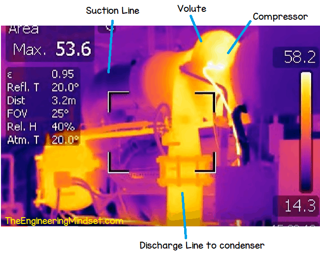
Above you can see a thermal image of a centrifugal compressor on a chiller. Notice the cool, low pressure refrigerant entering into the compressor but as it leaves through the volute and discharge line its temperature has increased.
The compressor is going to compress the refrigerant particles together which is going to make it highly energetic, and increases the temperature. Think of it as packing a lot of thermal energy into a smaller space. That is absolutely key to the operation of a chiller.
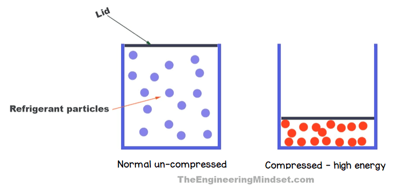
Imagine there is a cylinder full of refrigerant gas. As we move the lid and push it downwards, the particles become more closely packed and energised, there’s a lot of collisions occurring between the particles. If you’ve ever used a bike pump you’ll know that the pump will become hot as you force the air into the inner tube.
The reason that high temperature is important is because heat flows from hot to cold. We need the chiller to get rid of the buildings unwanted heat.

The condenser water circuit flows between the condenser and the cooling tower. The cooling tower disperses the heat into the atmosphere. The condenser water leaves the condenser at around 32C and returns at around 27C to pickup more heat.
Because heat flows from hot to cold, that means the refrigerant coming out of the compressor needs to be hotter than the returning condenser water. The only way to do that is to compress the refrigerant to raise the temperature. This will get the thermal energy into a much denser form which makes it easier to transfer over. The higher the temperature difference, the easier it is to transfer thermal energy.
If the refrigerant entering into the condenser was the same temperature as the returning condenser water, the chiller wouldn’t reject any heat so it wouldn’t work. The building will overheat and shut down.
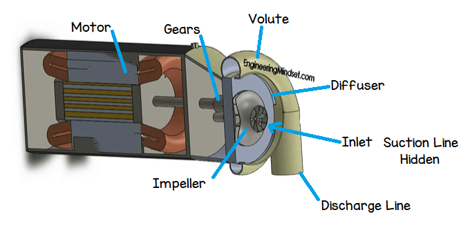
Part of the casing has been removed in the above model to show how the compressor works. The refrigerant flows in through the suction line (hidden) and is sucked into the impeller which rotates. The refrigerant rotates and is flung off the impeller blades.
The refrigerant then hits into the diffuser, which is a small gap running around the perimeter, between the compression chamber and the volute. The diffuser slows the high velocity refrigerant particles down and as that occurs it will transform the velocity into pressure. The refrigerant builds up in the volute and the constant force of the next incoming refrigerant pushes the refrigerant out through the discharge line and into the condenser.
The impeller will come in different diameter sizes. This variation occurs because the different refrigerants have different molecular weights. Different capacity chillers will require different sized lift or head pressure as well as the mass flow rate of the refrigerant through the chiller.
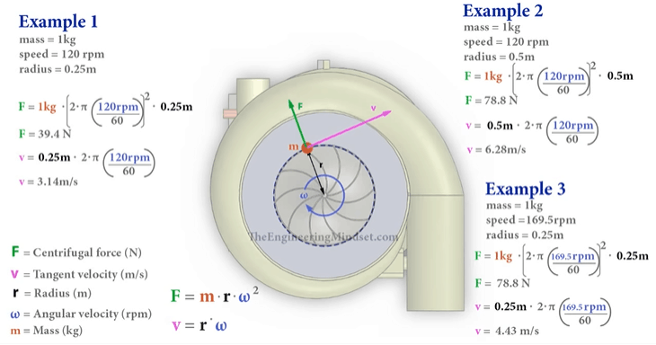
When the impeller spins, its going to have an angular velocity. If you spin something, it wan’t to move away from the centre as far as possible. Think of spinning a rock attached to some string. It moves outward. This is centrifugal force, which is actually just a combination of forces.
In the above illustration we’ve compared some different sized impellers. This calculates the centrifugal force as well as the tangent velocity. Check the video for detailed work through of these calculations.
How much work is done by the compressor?
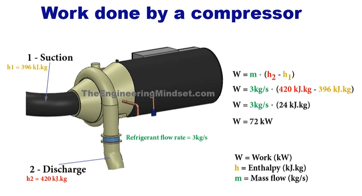
W can calculate that. It’s the difference in enthalpy between suction line and the discharge line, multiplied by the mass flow rate of the refrigerant.
I’ve shown an example above, however you can find a detailed worked example in the video below.











[…] the illustration above we have shown the main chiller components. The compressor, which is the driving force of the refrigerant around the system. The condenser which removes the […]
Thank you for putting out this information .
nice
Very nice
It’s very useful
Its Very helpful