

Voltage regulator. Learn how to make a 5V regulator using capacitors, LM7805 regulator and Schottky diode, learn how the circuit works and also how to build your own PCB printed circuit board, how to order a PCB and how to solder the boards electronic components together.
Scroll to the bottom to watch the YouTube tutorial
This is what happens when we supply to much voltage to our electronic components.

The components will burn out and even explode. To stop this, we need one of these.

A voltage regulator. And we’re going to show you how it works, how to design one and even turn it into a fully working, professional looking printed circuit board to use as a power supply and even charge a phone with it. You can even download a copy of our circuit board too HERE.
Designing the Circuit
The purpose of a voltage regulator is to keep a constant output voltage, even when the input voltage changes. Why is that important? Because the electronic components are only rated to handle a certain voltage.

Take this LED for example, if we connect it to a 9 volt battery, it will instantly be destroyed forever. That’s because of this thin wire inside the LED. Looking under a microscope we can see the voltage pushed too many electrons through the wire which caused it to burn out. To protect the LED we need a resistor. This will reduce the current.
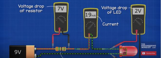
This is only a 10 ohm resistor, which is connected to our variable DC power supply. When we supply a small voltage, we see the LED is fine but as we increase this, the resistor burns into flames and the LED will be destroyed. So, using a resistor works well but the voltage must remain fairly constant. We therefore need a way to ensure a constant output voltage even when the input voltage is varied. Lets say we want to maintain a constant 5 volt DC supply and enough current to charge a simple cheap phone. We want to be able to connect this to multiple voltage sources such as 9 volts or maybe 12 volt batteries. To achieve that we need to use an integrated circuit component. There are lots to choose from, which can all work in different voltages, but from a bit of research we found this one. The LM7805.
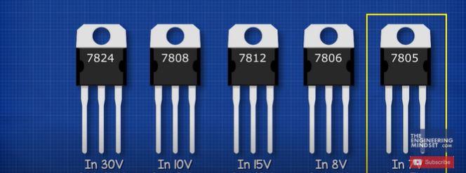
This can maintain a constant 5 volt DC output and up to 1.5 amps of current. This component can be connected to any DC supply voltage between 7 and 35 volts. So its perfect for our needs. It has three pins. Pin one is the input for unregulated voltage. Pin 2 is the ground pin and pin 3 is the regulated 5 volt output. The manufacturer recommends a capacitor on the input and the output. It notes that the input capacitor is required if the regulator is far away from the power supply filter. We are going to be using some long wires to connect the battery so we will use the recommended 0.22 microfarad capacitor. This is an electrolytic capacitor. We can use a slightly larger capacity version but we don’t want to use a smaller one. The capacitor is going to help smooth out interruptions to the supply and also low frequency distortions. In this simple example, you can see the LED turns off instantly when the power is interrupted. But if we place a capacitor in parallel with the LED the LED will remain on because now the capacitor is discharging and powering the LED.

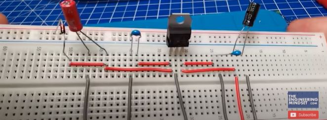
So, the LED is almost unaffected by the interruptions. We’re going to add another capacitor in parallel on the input side. This is a bypass capacitor. This is placed very close to the regulator input pin. This will be a small ceramic capacitor which is typically 0.1 microfarads. The purpose of this capacitor is to filter out the noise and high frequency distortions from the power supply. As we might not always get a perfectly flat DC supply. We will also add another 0.1 microfarad bypass capacitor on the output side as well as 10 microfarad electrolytic capacitor. This is just a typical value used for this purpose. We could use a slightly higher capacitor version if we wanted to but this will work fine. These are going to help ensure we have a clean output on our connected circuit. We will also add a protection diode on the input side. This will help protect the circuit if we connect the power supply the wrong way. To show it works, if we connect this incandescent lamp to a power supply, it will illuminate. We can reverse the leads and it will also illuminate. If we place a diode on the red wire and connect this to the positive, it will again illuminate. But now when we reverse the leads, the diode blocks the current and the lamp remains off. So we can use this to protect the circuit. We can use a rectifier diode or a Schottky diode. Here you can see we’ve placed two LEDs, each connected to a different type of diode. As we slowly increase the voltage, we see the LED connected to the rectifier diode is not as bright. That’s because this type of diode has a large voltage drop. If we measure across the Schottky diode, we have a voltage drop of around 0.3 volts and the rectifier has around 0.66 volts. So its better to use a Schottky diode for this application. Now we can lay all these components out on a breadboard to test it out like we’ve done here. And once we are happy that it works, we can now turn this into a printed circuit board.
Designing The Printed Circuit Board
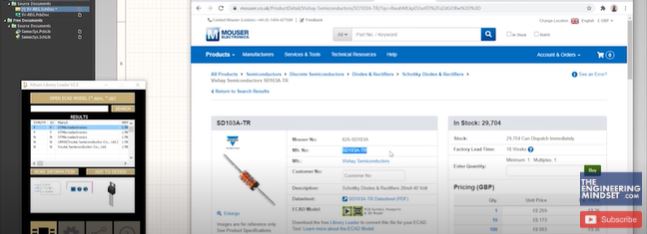
We’re going to be using Altium Designer for this tutorial as they have kindly sponsored this article. All our viewers can get a free trial of this software using the link HERE. So open Altium Designer and click File, New Project, then give the project a name. Right click the project and add a schematic, then right click again and add PCB. Now right click the schematic and save this. Give it the same name as the project. Then also right click the PCB and save that too with the same name. Now we need to add the components. We can use the components tool on the right hand side but we’re going to use an add-on which will make it a little bit easier. So we find the parts we require, we’re using Mouser but you can use whoever you wish. We’ve found a 22 microfarad capacitor so we take this part number and insert it into the library loader and click search. It then finds the component so we click ‘add to design’. It will place the component in the lower corner so we just need to move it into position. Then we rename the component just to make it easier for us. Now we do the same for the other input capacitor, copy the part number, and search for it, then add it, move it and rename it. Then we find the regulator, and add this to our design, and then we find the protection diode and add this to our design. By the way we’re using this one but we would recommend you choose one with a higher current limit.
And then we find the output capacitor, we add this and then we rename it. We now need to find the connection terminals and we add this too. We now need another capacitor on the outlet so we select the existing one and copy and paste that, and then move that into position. And we do the same for the connector type on the input side. Now we just rotate the components, so select the input connector and press the space bar to rotate it. Then we rotate the diode, then we can rotate the capacitors but do make sure that the plus symbol always goes to the positive power supply. The other ceramic capacitors do not have a polarity so these ones can face either way but we’ll keep it in this order. Then we rotate the regulator and we’ll also move the text, then we rotate the next capacitor, and the other capacitor. And now we just move the components into position. Now click the wire tool and start to connect the components together, bringing the ground wire around to the regulator. Then we add a ground symbol to this wire. Now use the wire tool to connect the output side as well. Now add the annotation for the input supply which is VCC then add the annotation for 5 volts on the output side, and rename this. We can then add some text for the ‘input voltage’ and also the ‘output voltage’ too. Now we need to number the components so click Tools, Annotation, Annotate Schematic. Then select Down, then Across, and then update the change list, click ok, accept the changes, then validate the changes. Then execute the changes and close. Now we see the components are all numbered. Next we need to validate the design. So click Project and then Validate Project. If we click View, Panels and then Messages, it tells us the compilation was a success with no errors. So now click on the PCB and click Design, and then import changes. Then validate the changes and then click Execute Changes. The components are placed in the lower corner, just click the box and delete it. Looking at our schematic we have the Connector J1 on the input so we’ll move that. Then we have the diode and capacitor 1, and capacitor 2, so we’ll move these into position also. Then we have the regulator, then we have capacitor 3 and 4 and then we have the output connector. We now rotate the components to make the route for our electricity to flow. We can switch to 3D mode to check how it looks. Then we can align the components to improve the appearance. Now click down here and in the new window, select mechanical layer. Right click and create new layer, and name it Cut Out. Change the settings and then close. Now select your layer down the bottom, then click Edit, Origin and Set. Then click the top corner of the circuit board. Now click Place and Choose Line. Draw a line around the components. Then while holding Shift, click on the 4 lines. Then click Design, Board Shape and Define Shape. We can then also see it in 3D. Now ill just change the text size so it doesn’t print too big. Now click on top layer and insert some text, and we’ll name this 5 volts and we can just rotate that. We’ll also do the same for the ground text. Looking at the input side of the board we’ve just realised that the input connector is the wrong way around, we can see that in the 3d view, we just missed that earlier so we’ll just correct that now. Then we add the ground and the VCC text to the board. Now click Route, Auto Route and select All. It then adds our route to the board. We can also move the route if we want to. Now we go to Tools and Rule Checker. Click Run, it loads a report and tells us that we have two problems on the silk and solder mast clearance. We go Design, Rules, Silk to Mask then change the value, click on Apply, Ok, then run the rule checker again. Now we see there are no errors. We can see the route in the 3D design now also. So lets save that. Click on your schematic and then click File, Smart PDF, then choose the schematic. We’re turning off the bill of materials but you can leave that on if you want to. Click Finish and it generates a PDF of our design, close that and then click on the Fabrication output, choose Gerber files and then choose the project. Now click that and change it to Millimeters, then on layers you can leave it as it is, but we’re going to select all the layers and click OK. Click on folder structure, and then link the file, click generate and that’s it. We’re done! We are ready to have our circuit board printed.
Manufacturing a PCB.

Now we need to order our PCB. We’re using JLCPCB who have also kindly sponsored this article. They offer exceptional value with 5 circuit boards for just $ 2 dollars, check it out HERE. We’re just changing the shipping destination and currency to the UK as that’s where we’re based, but you can choose your own country and currency. Now we simply upload our Gerber files and it will produce a preview. We have a number of options to customise the product, we’ll choose the quantity and then we’ll leave the rest as default. Then we’ll save this to cart and go straight to the check out. We can choose the postage option to decrease the cost, but we want this very quickly so we’re going to order through DHL Express. Then we just submit our order, and pay and that’s it. Simple, done. A few days later our circuit board arrives in the post from JLCPCB ready for us to build. We must say it looks pretty amazing, we’re very happy with this service. Don’t forget you can also download a copy of our circuit board for free HERE.
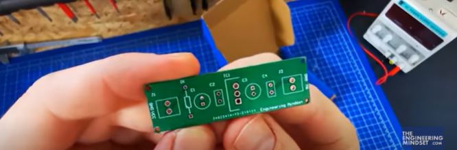
Putting the PCB Together
Building the PCB is pretty easy. We simply lay out our components, and we like to place them in order on this soldering mat. We’re also using this holder just to make it a bit easier to work with. Then we insert the components and we start to solder them one at a time. Just bend the legs slightly to hold them in place. As you solder the components in place, just inspect the soldered joints to make sure its ok and then you can trim the leads. And then after a few minutes we will end up with our completed circuit board which is ready for testing.

Testing the PCB
To test the circuit board we’ve connected a 9 volt battery to the supply. And the multimeter reads 5 volts on the outlet. If we reverse the battery we see 0 volts on the multimeter. So the diode is protecting our circuit. We’re happy with this so we place a small load on it and it works great. Now for the real test we connect a USB port on the outlet and we plug in a cheap phone. We can see the 9 volt battery is now charging the device. Using a USB tester, we can see that it is supplying 4.6 volts, and drawing a current of 0.26 amps. So it is working perfectly.


")

")

Awesome
can someone design a 5V 2amp ac to dc circuit and its PCB design.