

Almost every commercial building or industrial facility relies on the automation of their mechanical and electrical systems. This trend is only set to increase, especially as larger, smarter, more complex systems and buildings are constantly under construction.
Scroll to the bottom to watch the YouTube tutorial
So how do we control these systems and what devices are used to achieve that. That’s what we’ll be covering in this article, which is sponsored by tele controls.
TELE Controls are one of the leading manufacturers in the automation industry since 1963. Their technology is compatible with every PLC, HMI and controller on the market, which reduces PLC programming time and saves valuable storage by dealing directly with smaller automation tasks.
Click here to learn how Tele’s products can make the best out of our PLC application. You can contact them at [email protected] or even via linkedin.
What is a PLC
PLC stands for programmable logic controller. There are many variations but they typically look something like this.
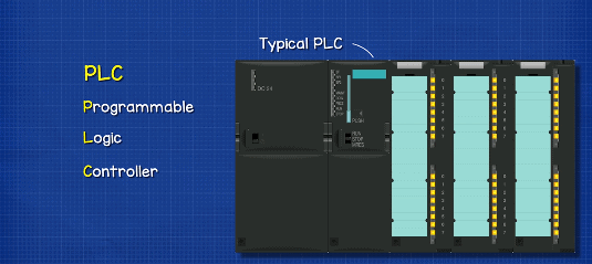
A Programmable Logic Controller is basically a small computer that can carry out pre-programmed outputs based on inputs and a set of specific rules.
They are used in commercial and industrial applications to control systems with minimal and sometimes even zero manual intervention. The operation can be a simple on off control based on the status of the input or a more sophisticated response based on calculations, sequence and logic.
Why Do We Need PLC’s?
Before PLCs, control was carried out via banks of relays. Each relay controlled dedicated inputs and outputs based on physical wiring. Relays would control other relays to form logic controllers. For example with a simple AND gate, only when 2 inputs are energised, this one AND this one, does the relay output energise. These inputs could be sensors or they could be outputs from other relays.
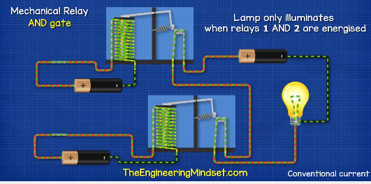
To change the operation, the physical wiring had to be changed, so the physical connections had to be altered if a different response was required.
These old banks of relays were vast in size and very complex. This is an example of an elevator relay bank. And this is the relay bank from an old electrical substation.
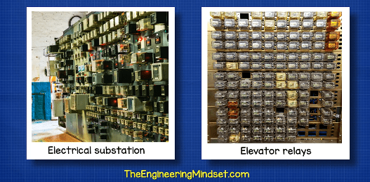
As you can imagine, these are not going to be easy to change and finding faults can be difficult and very time consuming.
With the invention of solid-state electronics and microchips, the command logic part of the banks of relays could be replaced with software logic and so PLC’s quickly took over.
PLCs vary widely on their application but they all monitor their inputs, then make a decision based on a stored set of rules and from those, they then output commands to automate a process.
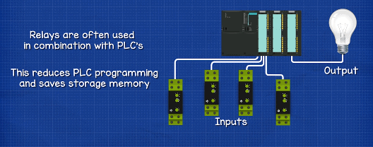
We often find relays used in combination with PLC’s. The relays can directly deal with the automation task and communicate with the PLC. This will reduce the amount of programming required on the PLC and also free’s up storage space.
PLC’s are widely used, for example, when you check your bag in at an airport. The bag is given a bar code and enters the conveyor belt. A PLC scans the barcode and, based on a set of rules, decides if the bag is diverted to either the domestic or international route. The next PLC scans the barcode and decides which city the bag needs to be diverted to. The next PLC decides which gate it also needs to be diverted to. And If it all of this goes to plan, then the bag will arrive at the correct gate.
Main Parts of a PLC:
First, we have the input modules or field sensors. These are the physical connections between the outside world and the PLC. These can be:
Digital inputs, such as
- Simple On – Off switches
- Bi metallic temperature strips
- Presence or motion sensors
- Or even a Float switch
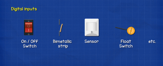
These digital inputs can only provide information on whether something in on or off, nothing in between. For that we would need an Analogue input. For example a simple control knob which ranges from 0% to 100%. This will go through a voltage transformer to give 0v at 0% and 10v at 100%. The PLC can scale the input to match the ‘sensitivity’ required for very accurate output control.
It could also convert the voltage into current using a resistor and Ohm’s law. The amount of current, usually measured in milliamps, tells the PLC whether something is performing between on and off.
These inputs could be for example;
- in a Thermocouple or a Resistance Temperature Detector.
- It could be a Pressure sensor
- Or perhaps a Strain gauge
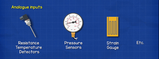
These voltage or currents are converted to a digital equivalent number that can be understood by the CPU. We will look at that a little later in this article.
Input modules will perform 4 basic tasks;
- They sense when a signal is received.
- They convert the signal voltage into the correct signal for the CPU.
- They isolate the PLC from fluctuations in the input voltage or current signal.
- They send a ‘corrected’ signal to the CPU.
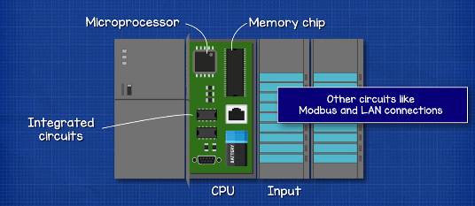
The CPU or Central Processing Unit is the brains of the operation. It holds the programme, or software, that decides what outputs are required by applying rules to the input signals.
The CPU typically consists of;
- A microprocessor, which does the work, based on the input value and the logic in the programme.
- A memory chip to store the program, this will also store the output history, any faults or alarms etc.
- Then we also have other integrated circuits, these can be for things like Modbus and LAN connections which allow us to remotely communicate with, reprogramme or monitor the device.
Then there’s the Output modules or Field Output Devices. This is providing the signal to the device we are controlling, for example a
- A simple indicator light
- A solenoid valve
- A motor starter
- A variable frequency drive
- etc
There are some other parts such as:
A battery to keep the PLC alive in the event of a power failure.
There might be a small screen for a user interface, to allow some configuration.
There will need to be a Time clock & Calendar to operate a device at the correct time
And there will also need to be a power supply to provide the low voltage used by the CPU as well as the Input and Output modules.
By the way we have covered, variable frequency drives, motor starters and solenoid valves in detail in our previous articles. Check them out HERE.
PLC Operation.
The basic operation of a PLC is to perform a pre-programmed output, depending on the input signal, by following a set of rules. The PLC completes the following stages in its basic operation.
First, there is the input scan, which detects the state of the inputs. Then, the program scan, to see what needs to be done. Then it will execute the program logic, to actually implement what the rules state. Then it must update the outputs, to operate output devices based on the program requirements. Finally, the housekeeping, for self-diagnostics, communications, updates and reporting.
The Scan time, which is the time it takes to complete all the stages, depends on the sensitivity, the resilience and systems processing time. Analogue inputs tend to take longer to process compared to more simple digital on off inputs.
For example, a water tank might have a fast scan time of 2 milli seconds and this will prevent over filling. But a room temperature control can be much slower, perhaps 100 milli seconds.

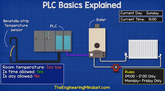
Example 1: Simple response example
Let’s see an example of a simple response. We have a bi-metallic strip temperature sensor, a PLC and a boiler. The bi-metallic strip bends as it becomes hot and cold so we can use this to detect if the room is at the desired temperature and from this, control the boiler.

When the room is at the correct temperature, the circuit is complete and the PLC receives a signal, so the boiler is off. When the room temperature drops, the circuit is no longer complete and the PLC detects this change on the input. It reacts by sending an output signal to turn the boiler on. This is very simple and we could also use a simple relay to achieve this.
However, a PLC is better because it has a time function, so it can check the time before switching on the boiler. For example, the building might be empty at night and on weekends. So, we don’t want the boiler to turn on then. The PLC is told the room is too cold, it checks the time and date to see if it’s allowed to turn on, and then based on this, it decides whether to turn the boiler on or leave it off.
We can then add extra functions and inputs. For example, a motion sensor on the input. The thermostat tells the PLC the room is too cold. The PLC will check the time to ensure it is allowed to turn the boiler on, and now it can also check to see if the room is occupied. For example, there could be a public holiday that isn’t listed on the calendar. The building is empty and so the boiler doesn’t need to turn on.
Example two: Advanced response.
In this next more sophisticated example we have a thermistor, the PLC as well as an actuator valve. The thermistor can provide a temperature scale rather than the simple on off input like the bi-metallic strip. The actuator valve can open anywhere between 0 and 100% to control how much hot water is provided to heat the room.
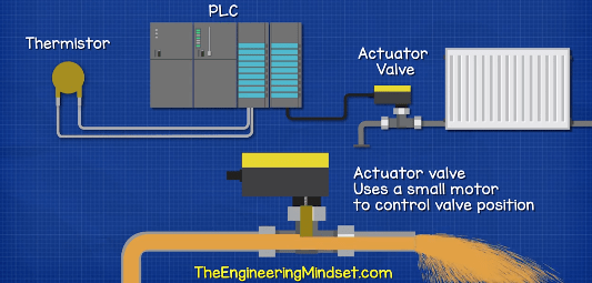
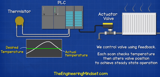
For this we would use a PID control loop. Which stands for Proportional, Integral and Derivative control. We won’t go into too much detail on PID’s but essentially this will control the valve position, to ensure it only opens enough to suit the difference between the rooms desired temperature and the rooms actual temperature.
For example, if the room temperature dropped very slightly, we don’t want the heating valve to instantly open 100%, because the room will heat too quickly and this will overshoot the desired temperature. At this point it will then instantly turn off and repeat this cycle. Instead we want the valve to gradually open, in proportion to the demand. So, if there is a small temperature difference, the valve slowly opens a small amount. If there is a large temperature difference the valve opens further and faster. It then decreases as it approaches the desired temperature until the valve finds the perfect position to maintain the desired room temperature.
Example 3: Complex Response
Let’s see a more complex example. In many commercial buildings, the heating or cooling system will use a control strategy known as an optimiser. This learns, over a period of time, how quickly the building heats up and cools down. It then starts the heating or cooling system at the optimal time, before the building will be occupied. For example, if the staff are due to turn up and start work at 9am, the heating system knows that it will need to turn on at 7am to ensure the rooms are all the correct temperature.
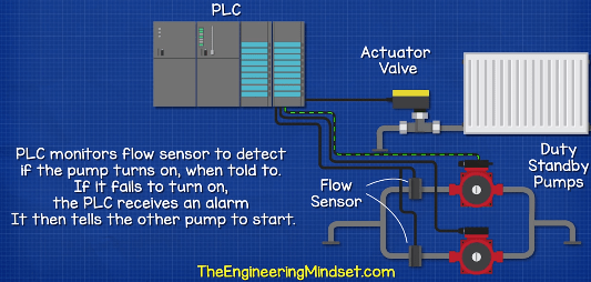
Let’s say this system has a PLC with the optimiser software installed. This controls an actuator valve for the heating system. This system also has two pumps, which are setup in duty and standby configuration so only one pump runs at a time. The PLC will decide which pump to turn on, based on whichever has the lowest number of previous run hours. The PLC will monitor a flow sensor to detect if the pump turns on when told to do so. If it fails to turn on, the PLC receives an alarm and it will cut the power. It then tells the other pump to start.
However, before the heating system and pumps start, the PLC will check with the clock, should the heating turn on today and if so, at what time will the building be occupied. The clock says yes, the scheduled occupancy time is 9am. The PLC then checks the current temperature of the room and calculates the difference between this and the desired temperature. It then checks the outdoor temperature to calculate how long it will take to heat the building, because on a very cold day, there will be a greater heat loss so it will take longer. From this, the PLC calculates what time it needs to turn the heating system on, so that the building is at the desired temperature, ready for 9am.
By the way we have covered duty and standby pumps and relays in our previous article. Do check that out HERE.
Advantages of PLC’s
There are many advantages of PLCs. But some of the main ones are as follows:
The control software is stored locally, so in the event of a building energy management system failure, the PLC can carry on.
The connections between the PLC inputs and outputs are made by the software and not by lots of physical wires.
PLC installations are smaller than hard wired relay banks, but can still use relays where needed
PLC’s are much easier to reprogramme.
Fault finding is easier and faster
You can load the same programme onto multiple PLC units to save time
You can also expand the inputs and outputs with more cards.


")


")

")

i really love all your videos and everything about the videos is amazing the editing, the content, the explanation….literally everything……PAUL you have to realize this simple and very obvious fact………..”YOU ARE THE CHOSEN ONE”…….lol….:)
Jokes apart bro i am lucky to have your guidance through these amazing videos.
Insightful. I work in a plastic processing factory. I understand it better now. PLCs can be used to convert manual machines into Semi-automatic/automatic machines.
thank you
Is there a way to get all this info, all the building automation lessons on paper? Gotta controls interview coming up soon and I want to be as informative as possible.
Detailed and amazing explanation. i found your videos impressive.