Learn how to make a simple solid state relay using an LED, a LDR and resistor. Shown with calculations.
Scroll to the bottom to watch the YouTube tutorial.
This circuit uses a light dependent resistor and a white Led. The LDR varies its resistance depending on how much light it is exposed to in darkness. It has a very high resistance, bright light. It has a very low resistance. This white Led is rated for 20 M.
If I connect this to the DC bench power supply, we can see it requires 3 volts to achieve that 20 milliamps. When I test this LDR, we see that with a dim light. It’s around 40kilohms of resistance. When I hide it in my hand, it’s around four mega ohms, and with two hands completely covering it, it’s around nine mega ohms. However, when I shine the white Led onto the LDR, it’s around 66 ohms.
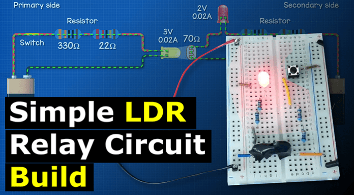
If I wrap my fingers around them both, then it’s around 70 ohms. So on the primary circuit, we need a white Led, which has a voltage drop of 3 volts and uses 0.02 amps. We will control this with a switch and use a nine volt battery to power the circuit. The resistor is found by 9 volts subtract 3 volts for the Led, which gives us 6 volts.
This will be the voltage drop of the resistor. The circuit current is 0.02 amps. So 6 volts divided by 0.02 amps is 300 ohms. Now this circuit will work fine on 20 milliamps, but I’m going to use a slightly higher resistor value to reduce the current of the LED.
This will also slightly reduce the brightness of the LED. I’m going to use a 330 Ohm and a 22 Ohm resistor. These will combine to form 352 ohms of resistance. So to check that 6 volts divided by 352 ohms is 0.017 amps or 17 milliamps.
I place the components into the circuit and it looks like this. The current will flow through the circuit like this; shown using conventional current. When I press the switch, the Led illuminates. On the secondary side we have a red Led with a voltage drop of 2 volts and a current of 0.2 amps. This will turn on to indicate the circuit is working.
Replace the LDR opposite the white Led. This will provide a resistance of approximately 70 ohms when exposed to the light. To find the resistor for the Led, we simply need to do 9 volts subtract. 2 volts, which is 7 volts, 7 volts divided by 0.02 amps is 350 ohms. 350 subtract 70 ohms for the LDR gives us 280 ohms. Instead of this I’m going to use two 150 ohm resistors which equals 300 ohms. so assuming the LDR is 70 ohms; we have 370 ohms of resistance. 7 volts divided by 370 ohms is 0.019 amps.
So if I place the components on the secondary side of the circuit board, it looks like this. Notice the red LED is on. That’s because the LDR is receiving the ambient light from the room. To stop this, all we need to do is take some electrical tape.
Just cut off a few small pieces and wrap them around both the LDR and the LED. This will block the ambient light from the room and the LED is now off. When I press the button on the primary circuit, the white Led turns on. This shines the light onto the LDR, which turns the red LED on in the secondary side.


