

Learn the basics of relays to understand the main parts, the different types as well as how they work.
Scroll to the bottom to watch the YouTube tutorial.
For all your relay needs, check out Tele controls, who have kindly sponsored this video. Tele controls are one of the leading manufacturers in the automation industry since 1963. They offer some of the best solutions when it comes to reliable switching relays, and guarantee the maximum lifespan for your equipment.
Checkout their switching relay portfolio along with suitable relay bases and accessories. You can contact them via email at [email protected] or through linkedin to receive your free relay configuration cheat sheet.
For more information click HERE
What is a Relay and Why Do We Use Them?
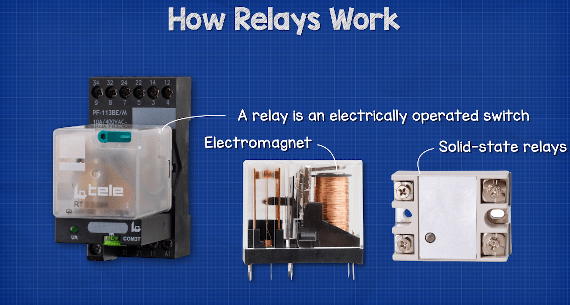
A relay is an electrically operated switch. Relays, traditionally, use an electromagnet to mechanically operate the switch. However, newer versions will use electronics such as solid-state relays.
Relays are used where it is necessary to control a circuit using a low-power signal, or where several circuits must be controlled by one signal. Relays ensure complete electrical isolation between the controlling and controlled circuits.
Relays are often used in circuits to reduce the current that flows through the primary control switch. A relatively low amperage switch, timer, or sensor can be used to turn a much higher capacity load on and off. We’ll see examples of this a little later in the article.
Main Parts of a Relay
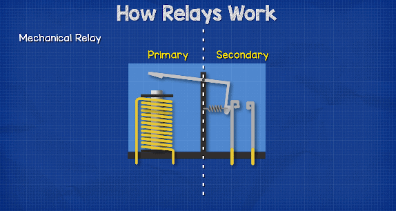
There are two main circuits in the relay. The primary side and the secondary side.
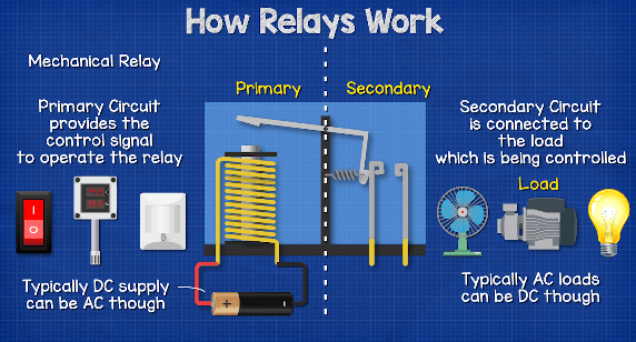
The Primary Circuit provides the control signal to operate the relay. This could be controlled by a manual switch, a thermostat or some type of sensor. The primary circuit is generally connected to a low voltage DC supply.
The secondary circuit is the circuit that contains the load which needs to be switched and controlled. When we talk about a load, we mean any device that will consume electricity such as a fan, pump, compressor or even light bulb.
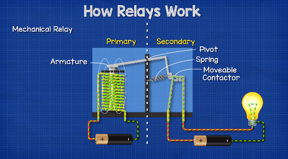
On the primary side, we find an electromagnetic coil. This is a coil of wire which generates a magnetic field when current passes through it.
When electricity passes through a wire it creates an electromagnetic field, we can see that by placing some compasses around the wire, when we pass a current through the wire the compasses change direction to align with the electromagnetic field. When we wrap the wire into a coil, the magnetic field of each wire combines together to form a larger, stronger magnetic field. We can control this magnetic field by simply controlling the current.
By the way, we have covered how solenoids work and even how to make your own solenoid in our previous article. Do check that out HERE.
At the end of the electromagnet we find the armature. This is a small component which is pivoted. When the electromagnet energises it attracts the armature. When the electromagnet is deenergised, the armature returns to its original position. Typically, a small spring is used to achieve this.
Connected to the armature is a moveable contactor. When the armature is attracted to the electromagnet, it closes and completes the circuit on the secondary side.
How an Electromechanical Relay Works
We have two types of basic relay, the normally open and normally closed type. There are other types of relays and we’re going to look at those later in the article.
With the normally open type, no electricity flows in the secondary circuit, the load is therefore off. However, when a current is passed through the Primary Circuit, a magnetic field is induced in the electromagnet. This magnetic field attracts the armature and pulls the moveable contactor until it touches the terminals of the secondary circuit. This completes the circuit and provides electricity to the load.
With the normally closed type. The secondary circuit is normally complete and so the load is on. When a current is passed through the primary circuit, the electromagnetic field causes the armature to push away which disconnects the contactor and breaks the circuit, this cuts the supply of electricity to the load.
How solid state relays work (SSR)
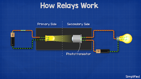
The operation of Solid State Relays or SSR’s is similar in principal, but unlike electromechanical relays, it has no moving parts. The solid state relay uses the electrical and optical properties of solid-state semiconductors to perform its input and output isolation as well as switching functions.
With this type of device, we find an LED light on the primary side, instead of an electromagnet. The LED provides optical coupling by shining a beam of light across a gap and into the receiver of an adjacent photo sensitive transistor. We control the operation of this type by simply turning the LED on and off.
The phototransistor acts something like an insulator and doesn’t allow current to flow, unless it is exposed to light. Inside the phototransistor we have different layers of semiconductor materials. There are N-type and P-type, which are sandwiched together. The N-type and P-type are both made from silicon but they have each been mixed with other materials to change their electrical properties. The N-type has been mixed with a material that gives it lots of extra and un-needed electrons, which are free to move around to other atoms. The P-type has been mixed with a material that has fewer electrons, so this side has lots of empty space which electrons can move to.
When the materials are joined together, an electrical barrier develops and prevents the electrons from flowing.
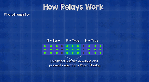
However, when the LED is turned on, it will emit another particle known as a photon. The photon hits the P-type material and knocks the electrons, pushing them across the barrier and into the N-type material. The electrons at the first barrier will now be able to also make the jump and so a current is developed. Once the LED is turned off, the photons stop knocking electrons across the barrier and so the current in the secondary side stops.
So, we can control the secondary circuit just by using a beam of light.
Types of Relays
There are many types of relays, we’re going to consider a few of the main ones as well as some simple examples of how they are used.
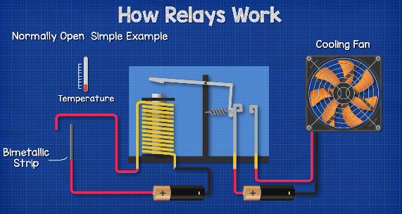
Normally Open Relays
As we have seen earlier in this article, we have the simple normally open relay. This means the load of the secondary side is off until the circuit is complete on the primary. We can use this for example to control a fan by using a bimetallic strip as a switch on the primary side. The bimetallic strip will bend as it increases in temperature, at a certain temperature it will complete the circuit and turn the fan on to provide some cooling.
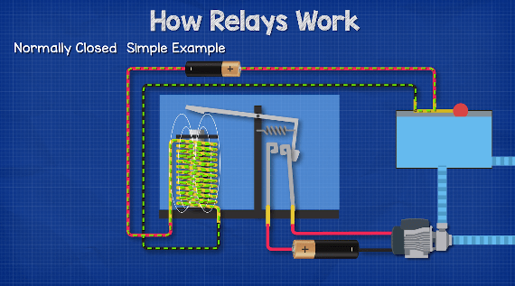
Normally Closed Relays
We also have a normally closed relay. This means the load on the secondary side is normally on. We could for example control a simple pump system to maintain a certain water level in the storage tank. When the water level is low, the pump is on. But, once it reaches the limit we require, it completes the primary circuit and pulls the contactor away, which cuts the power to the pump.
Latching Relay
In a standard, normally open, relay, once the primary circuit is de-energised, the electromagnetic field disappears and the spring pulls the contactor back to its original position. Sometimes, we want the secondary circuit to remain live after the primary circuit is opened. For that we can use a latching relay.
For example, when we press the call button on an elevator, we want the light on the button to remain on, so that the user knows the elevator is coming. So, we can use Latching Relays to do this. There are many different designs for this type of relay, but in this simplified example, we have 3 separated circuits and a piston which sits between them. The first circuit is the call button. The second is the lamp and the third is the reset circuit.
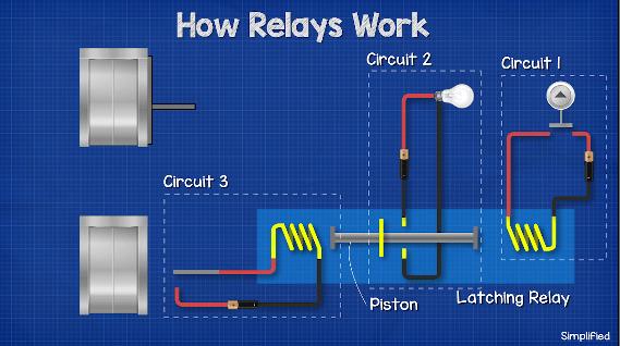
When the call button is pressed, it completes the circuit and powers the electromagnet, this pulls the piston and completes the circuit to turn the lamp on. A signal is also sent to the elevator controller to send the elevator down. The button is released, this cuts the power to the initial circuit, but as the piston isn’t spring loaded, it stays in position and the lamp remains on.
Once the elevator car reaches the lower floor, it makes contact with the off switch. This powers the second electromagnet and pulls the piston away, cutting the power to the lamp.
Latching relays therefore offer the benefit of having positional ‘memory’. Once activated, they will remain in their last position without the need for any further input or current.
Double or Single Pole
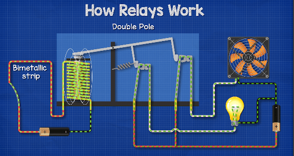
Relays can have single or double poles. The term Pole refers to the number of contacts switched when the relay is energised. This allows more than one secondary circuit to be energised from a single primary circuit.
We could for example, use a double pole relay to control a cooling fan and also a warning light. Both the fan and lamp are normally off, but when the bimetallic strip on the primary circuit gets too hot, it bends to complete the circuit. This creates the electromagnetic field and closes both contactors on the secondary side, this provides power to the cooling fan as well as the warning light.
Double or Single Throw Relays
When dealing with relays, you will often hear the term “throws”. This refers to the number of contacts or connection points. A double throw relay combines a normally open and normally closed circuit. A double throw relay is also called a changeover relay, as it alternates, or changes, between two secondary circuits.
In this example, when the primary circuit is open, the spring on the secondary side pulls the contactor to terminal B, powering the lamp. The fan remains off because the circuit is not complete.

When the primary side in energised, the electromagnet pulls the contactor to terminal A and diverts the electricity, this time powering the fan and turning the lamp off. So, we can use this type of relay to control different circuits depending on an event.
Double Pole, Double Throw Relay
A double pole, double throw relay or DPDT is used to control 2 states on 2 separate circuits.
Here we can see a DPDT relay. when the primary circuit is not complete, terminals T1 and T2 are connected to terminals B and D respectively. The red LED and the indicator light are energised.
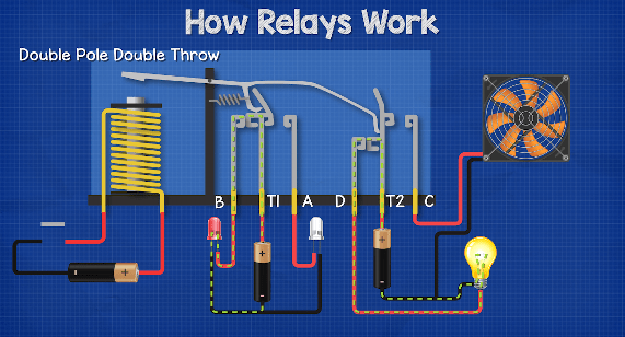
When the primary circuit is closed then T1 and T2 connect to terminals A and C, the fan turns on and the green LED is energised.
Suppressor Diodes (Flywheel Diodes)
Something we need to consider when working with electromagnets is the back EMF, or electro motive force. When we power the coil, the electromagnetic field builds up to a maximum point, the magnetic field is storing energy. When we cut the power, the electromagnetic field collapses and releases this stored energy very quickly, this collapsing field continues to push the electrons, which is why we get the back EMF. This isn’t a good thing because it can produce very large voltage spikes which damage our circuits.

To overcome this, we can use something like a diode to supress this. The diode only allows current to flow in one direction, so in normal operation the current flows to the coil. But, when we cut the power, the back EMF is going to push the electrons and so the diode will now provide a path for the coil to dissipate its energy safely, so that it doesn’t damage our circuits.


")


")

")
How can I get your book for electrical,a pdf one