

120V / 240V Split Phase residential electrical supply. In this video we’re going to be learning how split phase electricity supplies work to get both 120V and 240 Volts. We’ll look at how the electricity gets from the power station and to the property and then how it is connected around the house and each of the main components.
Scroll to the bottom to watch the YouTube tutorial video on 120/240V Split phase electricity
This system is used in north America so we’ll use their terminology and colour coding. If you’re from outside this region then you can still follow along but your electrical system works differently, we’ve covered this in a separate tutorial, do check that out here.
Warning
Remember electricity is dangerous and can be fatal, you should be qualified and competent to carry out any electrical work. Never work on hot/live electrical circuits.
So electricity is generated at the power station which is usually located far away. The power station generates AC alternating current and is connected to a step up transformer, this transformer increases the voltage to reduce losses and is connected to the grid. The grid carries high voltage electricity over long distances over to the towns and cities.
Once it reaches the towns and cities it will enter a step down transformer which will decrease the voltage to a safer level. From here it will be distributed locally into smaller circuits on different streets or groups of properties.
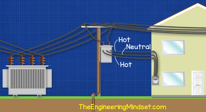
Connected to these distribution cables will be a smaller transformer, usually pole mounted, which again reduces the voltage down even further to a level safe enough for residential use. On the property will be an electricity meter which will quantify how much electricity has been used and the electricity company will use this to invoice you.
The transformer will be connected to the electricity meter by some cables which either run underground or overhead. These cable will be two hot wires and a neutral wire.
Inside the transformer we have two coils of wire. The primary coil is connected to the power station and the smaller coil will be connected to the property. The two hot wires are connected to each end of the secondary coil and the neutral is connected to the centre of the coil. Don’t worry about that for now, we’ll look at this again later in the tutorial to understand it.
Inside the property (sometimes outside) we will find a main service panel which is often also called a load center or breaker box.
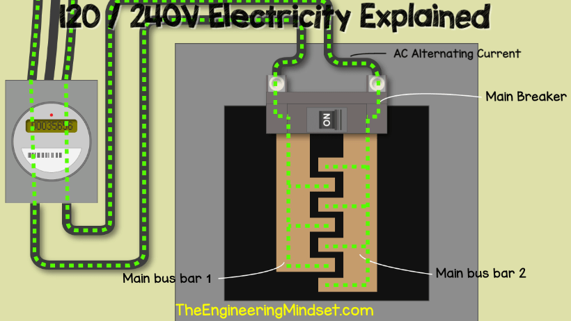
If we remove the cover and look inside, we will first find a main breaker. This is usually at the top of the panel but it might be at the bottom. The two hot wires from the electricity meter will connect directly to the lugs on the main breaker.
Coming out of the main breaker will be two main bus bars. These are basically exposed metal sheets which carry electricity to the circuit breakers.
These bus bar metal sheets, as well as the lugs, are not insulated, they are live/hot. The main breaker can be manually flipped to cut the power to everything downstream of the breaker. The main breaker will also provide overcurrent protection to the property, it is rated to handle a set amount of electrical current passing through it typically between 100 and 200 amps, if this is exceeded then it will trip automatically to try and protect the property and electrical circuits.
Inside the panel we will also have a neutral and ground bus bar. This is basically a strip of metal with lots of holes and screws in it. The neutral and ground wires will sit in the holes and the screws lock them in place.

In this example we have a block on either side of the panel. As this is a main panel the two bars can be joined together (Check with the NEC for exact details), so we have the connector bar to join the two bus bars. That way we have a shared neutral ground bar. Sub panels must be separated but that’s a topic for a separate tutorial.
From the electricity meter we will have the neutral wire connected to the lug on top of the neutral ground bar. Notice the green screw, this is bonding the neutral bar to the metal casing of the service panel.
The purpose of the neutral bar is to return the used electricity back to the transformer. It does actually get a little more complex than that because current is flowing backwards and forwards in AC current. If you want to go into the detail you can watch this video.
So the two hot wires will provide the electricity and once it is used it will return to the transformer via the neutral bar.
Now if we were to take our multimeter and connect one lead to a bus bar and the other lead to the neutral bar, we would get a reading of around 120V.


If you don’t have a multimeter then I highly encourage you to get one for your toolkit, it’s essential for any electrical testing and fault finding. Personally I would recommend this one as it’s a True RMS auto multimeter.
If we connect the multimeter leads to the other bus bar and the neutral bar we would again get a reading of around 120volts.
But if we connected the multimeter leads to the two bus bars then we will get a reading of double that at around 240 volts.
So why is that, whats happening here.
So when we look at how the transformer is connected to the main panel. We have the two hot bus bars connected to either end of the secondary coil in the transformer and then we have the neutral bus bar connected to the center of the secondary coil.
So basically when we connect across one bus bar and the neutral bar, we are only using half the coil, therefore we are only picking up half the electrical voltage the transformer can provide and we get 120 volts.
When we connect to the two bus bars we are connecting to the full length of the coil so we can pickup the full voltage which the transformer can provide. Therefore we get 240V.
If you want to learn how transformers work then tutorials on transformer basics, click here to see.
Coming back to the panel. Connected to the bus bars will be our circuit breakers. The circuit breaker controls the flow of electricity in individual circuits in the property and can be manually tripped to cut the power but it has two important features.
The first feature is overload protection. The circuit breaker is rated to handle a set amount of electrical current. When appliances or lights are connected to the circuit, they will each increase the current in the circuit. If too many things are plugged in or turned on then eventually the current will be more than the breaker can handle and the breaker will automatically trip to cut the power off, to only that circuit, and protect the property.
The second feature is short circuit protection. When the hot and neutral come into direct contact with each other the current will dramatically increase almost instantly. When this occurs, it creates a magnetic field which will trip the breaker and cut the power automatically.
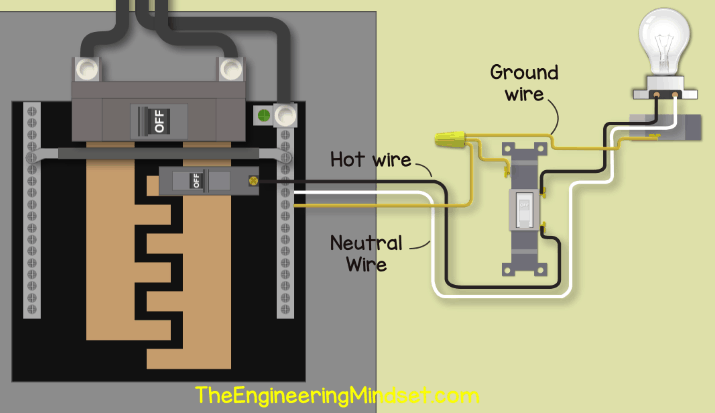
In the example of a simple lighting circuit, which is controlled by a switch. We take the hot wire from the circuit breaker and run this to the switch. We then run another wire from the switch and over to the light fitting. From the light fitting we have a neutral wire which carries the return current back to the neutral bus bar.
We take the ground wire from the metal casing of the ceiling box and the switch and we also join this into the neutral bar as in this case it is shared.
The purpose of hot wire is to carry the electrical current over to the light fitting. The purpose of the neutral wire is to carry the used electrical current back to the main panel and then back to the transformer.
The purpose of the ground wire is to provide protection for a fault current. If for example the hot wire came loose and touched the metal casing of the light fitting, the ground wire provides a low resistance path back to the panel. Without this, the electricity could flow through you if you touched the metal box. As the current flows through the ground wire it will increase the current and that will trip the breaker automatically.
So the electricity flows in through the hot wire, through the main breaker, down the main bus bar and into the circuit breaker. From there it flows along the hot wire, across the switch and light, then back along the neutral wire and into the neutral bus bar, then along the main neutral wire back to the transformer. This has been animated with AC alternating current where the electrons move backwards and forwards.
We’ve covered lighting circuits in detail in separate tutorials. Link for that here.
In addition to a circuit breaker, we will usually find a double pole circuit breaker which will let us connect to both bus bars to get the 240V which we can use to power larger appliances like driers, ranges and air conditioning units.
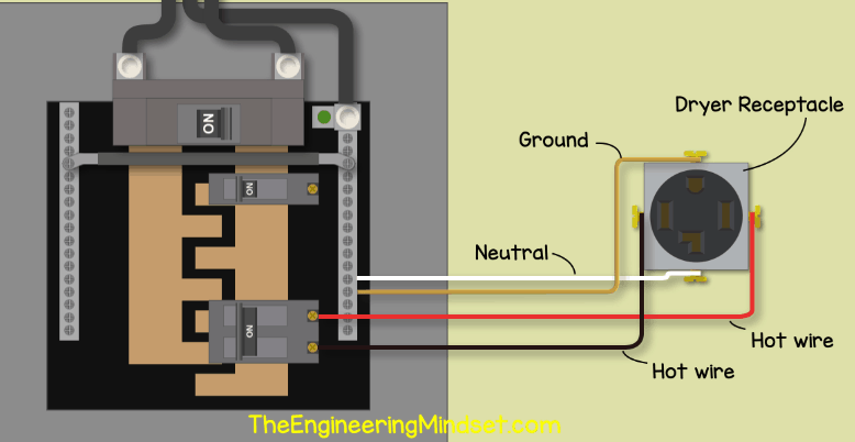
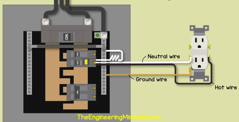
If we look at a drier circuit example, We run the red, hot wire, from the circuit breaker which is connected to main bus bar two, to the receptacle. Then we run our black, hot, wire from the other terminal of the breaker which is connected to bus bar one, and connect that to the receptacle also. In this case we have the neutral wire connected between the neutral bus and the receptacle which will allow us to get either 120V or 240V from the outlet. We then have a ground wire to provide a safe route for a fault current.
We can either connect across the two hot wires to get our 240V or between a hot wire and the neutral to get 120V.
We will also likely find a GCFI circuit breaker which stands for Ground Fault Circuit Interrupter. Depending on the model you buy, it will typically have a pigtail neutral wire connected to it.
GFCI’s are required on certain circuits where outlets are used in places like kitchens, bathrooms, hot tubs etc. Check the national electric code for exact details. The GFCI breaker has both the hot and neutral flowing through it. This way it can measure the current flowing in both wires and ensure they are equal. If they’re not then electricity is leaving the circuit and is possibly flowing through a person, to ground.
If we took a standard outlet, we would take our hot from the breaker and connect this to the outlet terminal. Then we take the neutral wire and run this back directly to the circuit breaker to a specific neutral terminal. We then connect the pig tail wire into the neutral bus bar, this will provide the return path. And of course we run the ground wire from the outlet back to the neutral ground bar.
We might also come across an AFCI circuit breaker. This stands for arc-fault circuit interrupter. These are required for circuits feeding bedrooms, hallsways, kitchens etc. Again check the national electric code for exact details.
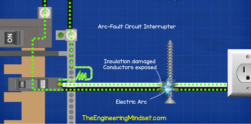
AFCI’s work by also being connected to both the hot and neutral wires. Inside the breaker is a circuit board which is measuring the circuit and monitoring for patterns which indicate an arc fault is occurring. These are installed pretty much identically to how we saw the GFCI breaker.
Under normal conditions the current flows through the hot, back through the neutral into the breaker, then through the pig tail and back through the neutral bar.
But if for example a screw was accidentally inserted very close to the cable and removed the insulation to expose the copper wires. The electricity could now potentially jump across or arc from the hot wire and into the neutral.
The arc is incredibly hot and causes most residential electrical fires. As the arc occurs it creates a unique signal in the electrical cable. The circuit break can detect this and it will automatically trip to cut the power.

Connected to the neutral ground bar will be a thick uninsulated copper wire which runs out the bottom of the panel and off to a ground rod which is pushed into the earth near the property. Under normal circumstances, no electrical current will flow through this wire, it’s purpose is to dissipate high static voltages from things like lighting, this way the electrical systems and equipment is protected from damage. Read more about that here.
Additionally we will also find a bonding wire to the metal water pipes in the property. This will provide a safe route for electricity to flow should a hot wire come into contact with the metal pipe and prevent a person being electrocuted if they were to touch the pipework.


")


")

")

I really commented you guys for the nice job{specially beneficial for others including me} today, I really enjoy learning on this website on electrical engineering, thank you for helping others keep updating their minds [like me] so keep updating this very best website.
Am a technician in South Sudan [Africa]
What would make one leg register 111 volts and the other 130 volts?
This actually happened to me. The power company came and performed some load tests at the meter, and they detected that the neutral wire between the transformer and my house was damaged. They had to replace the wire, and that took care of the problem.
[…] the center of the transformer, the neutral conductor connected. the ground by tapping. An AC line voltage of 120 volts generated. which exits the 180-degree phase with each other when required. By […]
can I replace the evaporator innerpart with a plate heat exchanger
Hi
Nice article on electricity