

Learn about electrical current to understand the different types, the symbols used to represent them, how to measure current and how safety devices are used to protect us and our electrical circuits.
Scroll to the bottom to watch the YouTube tutorial.
What is Current?
Current is the flow of electrons in a circuit. To use electricity, we need electrons to flow in the same direction around a circuit, we usually use copper cables to form the circuit because copper is a very good electrical conductor, which means the atoms that make copper have a loosely bound electron in that outermost or valence shell, which is free to move around inside the metal.
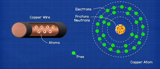
This free electron is very easy to move, which is why copper is so popular. It’s so easy to move that it will naturally move to other copper atoms by itself. But this occurs randomly in any and all directions, which is of no use to us. We wrap copper wires in rubber because the rubber is an insulator, which means it does not allow free electrons to pass through it. That provides a barrier and keeps the electricity within the wires and away from us.
For us to use electricity to power our devices- we need lots of electrons to flow in the same direction along a circuit. We can then place things like lamps in the way of these electrons so that they have to flow through it and generate light and heat in the process. To do this, we need to force the electrons to move and we can do that by applying a voltage. Voltage is the pushing force, it’s like pressure in a water pipe. The more pressure we have, the more water can flow, the more voltage we have, the more electrons can flow.
We can measure pressure without there being any water flowing and we can measure voltage without there being any current flowing. But we can’t measure how much water is flowing if no water is flowing. And we can’t measure the electrical current if no electrons are flowing, if we take a copper wire. There is no voltage difference between the two ends so the free electrons move around randomly. This random movement is not considered a current. But if we take a battery of, say, one point five volts and connect the wire across the two terminals, then there is now a difference of one point five volts across the wire.
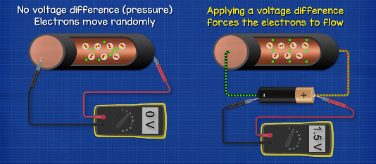
And this difference is going to force the electrons to flow in the same direction. We’ve covered the basics of voltage in detail in our previous article. Do check that out HERE. So we need a lot of electrons to flow along a circuit and through our lamps to get them to shine brightly, however, the cables and lamp can only handle a certain amount of electrons passing through them, just like a pipe is rated to handle a certain amount of water passing through it or a certain pressure.
If it were to exceed this, then the pipe will just burst. Likewise, if too many electrons pass through the cable or the lamp, then they will burst or burn out. We refer to the flow of electrons as current, and we measure this in a unit of amperes, although you usually just hear people say amps. This is also represented with a capital A..
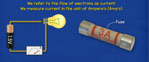
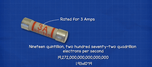
For example, this fuse has a three and a capital A. which means it’s rated for three amps of current. We’ll look at how fuses work a little later in this article.
Conventional Current Versus Electron Flow
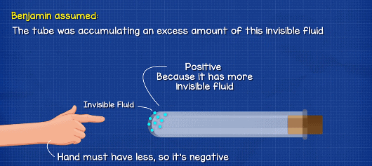
Something that’s going to cause you great confusion when you’re learning about electricity is the difference between conventional current and electron flow. These are both theories of how electricity works. When Benjamin Franklin was first experimenting with electricity, he had the idea that something must be flowing inside the materials, he was given a glass tube. And when this was rubbed with a cloth, it seemed to accumulate this strange, invisible fluid because when someone else touched the tube, they received a small shock.
We now know this as static electricity. But at the time, Benjamin Franklin assumed that the tube was accumulating an excess amount of this invisible fluid. So he considered this to be positive and the person touching it must have less of this fluid, so they were considered negative. So he said, ‘OK, I guess this end is positive and this end is negative and electricity flows from positive to negative’. And this does make sense because water is a fluid and it flows from a high level to a low level.
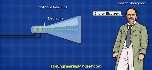
Soon, manufacturers started producing batteries based on his work, and so they also said, well, this end is positive and this end is negative and we still use this naming convention to this day. This became known as conventional current because it’s the conventional theory of how electricity flows. However, as science evolved and experiments became more precise, someone called Joseph Thompson discovered that this invisible thing moving inside the wire was a particle, and he named this particle an electron.
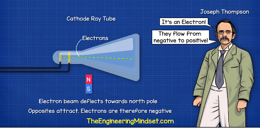
He also discovered these electrons were actually flowing in the opposite direction from the negative to the positive. Benjamin Franklin didn’t realize the silk cloth was actually removing electrons from the glass, so they were actually flowing from the person and to the glass tube. Joseph Thompson’s theory became known as electron flow because it’s the flow of electrons and so what’s actually occurring, is these electrons are flowing in a circuit from the negative to the positive terminal and not the positive to the negative.
However, it doesn’t really matter what’s moving inside the wire or in which direction, because the electrical engineering formulas we use do not take this into account. So they will still come out with the same answers. It’s also a little bit too late now to change the names of the terminals of all the batteries in the world. So everyone just kind of ignored this and we continue to teach and use conventional current. Some books might show you both.
So you need to remember that whenever we talk about electricity or whenever we design a circuit or even look at an electrical circuit drawing, we always default and assume conventional current is occurring. But engineers and scientists know that the electrons are actually flowing the other way.
AC and DC Electricity
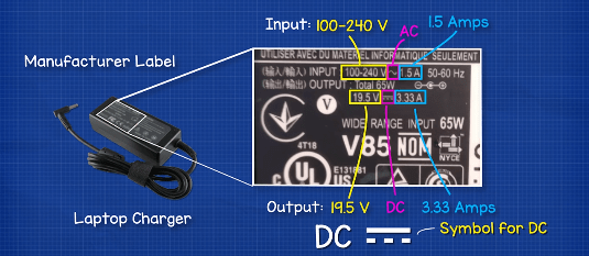
If you look on the plugs of your electrical devices, you should find labels from the manufacturers which tell you what the product is designed to handle. For example, this laptop charger tells us that for the device to work, it needs an input of between 100 and 240 volts and 1.5 amps of AC or alternating current, which is represented by this symbol here.
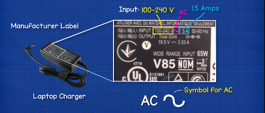
The Charger will then convert this to give an output of around 19.5 volts and 3.33 amps of DC or direct current, which is represented by this symbol.
AC and DC are different types of electricity, the plugs in your homes provide AC or alternating current. In this type the electrons do not flow in a continuous loop. Instead, they alternate between moving forwards and backwards, just like the tide of the sea. Your electrical devices, like laptops and mobile phones, will use DC electricity.
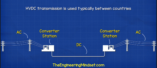
In this type the electrons flow in one direction only – directly from one terminal to the other. You can think of this like the flow of water down a river. In most cases, we transport electricity from a power station to the towns and cities using AC electricity because it’s easy to increase and decrease the voltage using transformers. And it’s also very efficient to transport electricity over long distances using this method. However, there are a few high voltage DC transmission lines being used, but we won’t go too much into detail on those.
We mostly use DC direct current for the circuit boards of small electronic devices like laptops, mobile phones and TVs. That’s because D.C. is easier to control and allow circuits to be smaller and more compact, many appliances will use a combination of AC and DC. For example, a washing machine will use AC for the induction motor, which is used to spin the tub with the clothes in. But the circuit board, which controls the settings, the lights, the timers, as well as how fast the motor spins, will use DC power.
We can convert AC to DC using a device known as a rectifier. This is extremely common in electronics. We can also convert DC to AC using an inverter and this is used, for example, with solar power systems. We have covered power inverters in great detail previously. Do check that out HERE.
People often refer to a river or the tide of the sea as having a strong current. It’s very similar to electricity.
A river with a lot of fast flowing water is said to have a strong current, the same of electricity. A cable with a lot of electrons flowing also has a high current. A river is able to handle a certain amount of water flowing through it. But if more water enters than it can handle than the river will burst its banks. The same with electricity, the cable will burst and burn out. Therefore, manufacturers need to be able to test cables and lamps to find out how much current they can handle.
We also want to be able to see how much current is flowing through our circuits, as well as being able to calculate this, we can measure this using an ammeter, and we measure the flow of current in the unit of amperes. But you usually hear people just shorten this to amps. So what is an amp? One amp is equal to one coulomb per second and one coulomb is equal to approximately six quintillion, 242 quadrillion electrons per second. OK, but what does that mean?
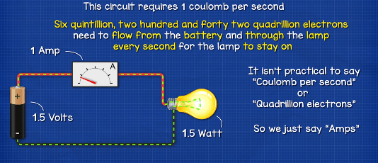
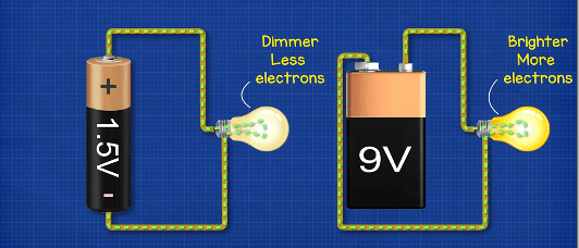
Another way to look at this is that to power this 1.5 watt lamp with a 1.5 volt battery requires a current of one amp. That means that the circuit requires one coulomb per second, which means approximately six quintillion, 242 quadrillion electrons need to flow from the battery and through the lamp every second for the lamp to stay on. But as you can see, it’s not very practical to say how many electrons per second are flowing. So engineers just say amps to save time. The brightness of the lamp will vary with voltage.
As we decrease the voltage, there is less pressure pushing the electrons so less electrons flow. As we increase the voltage, more electrons flow and the lamp shines brighter. But don’t forget, at a certain voltage and current, a lamp will burn out. To measure the current in a circuit, we need to connect an ammeter in series so that the current flows through it. Think of it like a water meter. The water in a pipe needs to flow through the water meter for us to know how much water is flowing.
Likewise, we need the electrons to flow through our ammeter, instead of using an ammeter, we’re going to use a multimeter as we can do a lot more with this device. I highly encourage you to get one of these for your tool kit. They’re an essential tool for any electrical engineer.
If we connect this 1.5 volt battery and this lamp, which has a resistance of one ohm, then we get a current reading of 1.5 amps.
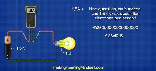
Which means nine quintillion 636 quadrillion electrons are flowing through the line every second. Because the components of this circuit are wired in series, the current is the same anywhere in the circuit, so we can take a measurement anywhere and it’s the same value. If we add another lamp to the circuit connected again in series and the lamp also has a resistance of one ohm, then we’re adding more resistance to the circuit. So it’s now harder for the electrons to flow through. And so we see a reduction in current. In this case, we get a reading of 0.75 amps, which means four quintillion 818 quadrillion electrons are flowing.
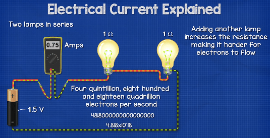
This circuit is in series. So again, we can move the multimeter and we get the same reading. If we now connect the circuit with two lamps in parallel, both with a resistance of one ohm and connect this circuit to a battery of 1.5 volts, then in the main wire from and to the battery, we get three amps.
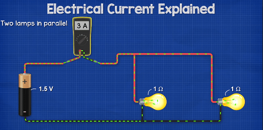
But on the branch of each lamp, we get 1.5 amps because the path of the electron splits. So they are shared between the two lamps. The path then merges again- So we get the combined total circuit current of 3 amps because both lamps have the same resistance, they have the same current. But for example, if A has a resistance of one Ohm and that B has a resistance of three ohms, then in the main wire we get an amp reading of two amps. In the branch for Lamp A, we get 1.5amps and in the branch for Lamp B, we get 0.5amps.
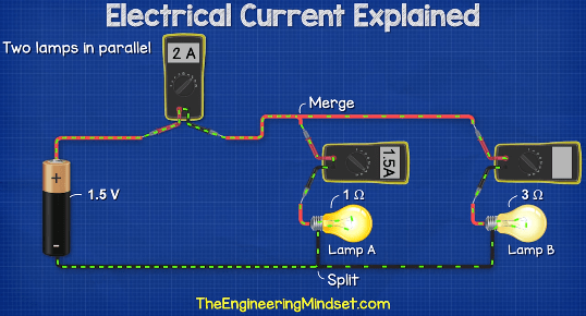
Notice though, that lamp B is dimmer. That’s because the resistance is higher, which makes it difficult for electrons to flow through. In both cases, the amps and the branches all add up and are equal to the total current flowing in the main wire to and from the battery. Therefore, we can add resistors to our circuits to restrict how much current can flow.
Resistors
Resistors make it harder for electrons to flow through a circuit, and that’s why we add resistors to the circuits because they reduce the current, it’s like having a kink in a pipe.
This will add resistance to the flow of water, which reduces how much water can flow through. And as the water is colliding with the pipe wall, it is going to lose energy. So we get a pressure drop. The same with a resistor. The material makes it difficult for electrons to flow through. The electrons are going to collide and waste energy so we get a voltage drop. This wasted energy needs to go somewhere, so it leaves as heat.
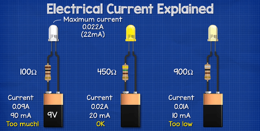
If we look at a resistor through a thermal imaging camera, we can see that heat leaving. For example, this LED is rated for a maximum of 22 milliamps or 0.022 amps. We want to connect this to a nine volt power supply. If we use a 100 ohm resistor, then the current would be 0.09 amps, which is too much. And the LED will burn out. If we use a 450 ohm resistor than the current is 0.02 amps, which is below the limit.
So that should be OK. If we use a 900 ohm resistor, then the current is 0.01 amps, which is far too low, so the LED will not shine brightly.
Fuses
Fuses, in a basic sense, have a thin piece of wire inside them, which is rated to handle a certain amount of current flowing through them. In this case, this one is rated to handle three amps or 19 quintillion 272 quadrillion electrons per second. If too much current flows in the circuit, then the fuse will burn out and this will open or break the circuit to protect the expensive electrical components, the fuse acts as a weak point and is very cheap to replace.
So you can find these mounted on circuit boards. And in the UK, plugs will often have a fuse built in for added safety.
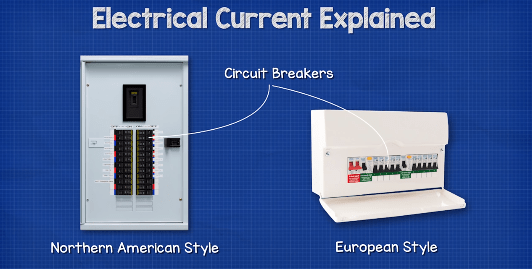
Circuit Breakers
We find circuit breakers in our electrical panels within our homes and places of work, circuit breakers are essentially a switch that automatically opens to break the circuit if too many electrons pass through it in either an overload or a short circuit scenario.
Overload Protection
With the overload function, if we slowly add more load to the circuit, we will eventually exceed the rating of the breaker and it will flip to cut the power and protect the circuit.
This is known as overload protection. Another feature of most modern circuit breakers is short circuit protection. In this case, if for some reason the positive and the negative wires come to direct contact, then we see a very large and instant surge in current because there is no resistance. The circuit breaker will detect this instant surge in current and will cut the power to cut the circuit.
GFCI and RCD’s
In North America, we find another device called a GFCI or a ground fault circuit interrupter. In Europe, this is called an RCD or residual current device.
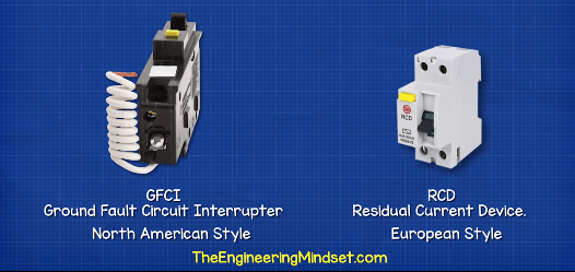
These basically monitor and compare the current in the supply and return wires to a circuit. If the current coming back is not equal to the current being supplied, then the electricity has found another path and is leaving the circuit. It could be passing through a person so the device cuts the power. This happens extremely fast and with a very small tolerance to help protect electric shocks and keep us safe.


")

")
