

Learn about the basics of the CAV system, to understand the main parts and how it works.
Scroll to the bottom to watch the YouTube tutorial.
What is a CAV System?
CAV stands from Constant Air Volume. It’s a type of HVAC air distribution system used in buildings where the volume of air suppled is kept constant but the temperature of the air is varied.

CAV is an older design method; we still find this used in existing buildings but it’s less common in newer buildings because VAV systems are now the preferred choice of installation. VAV stands for variable air volume. This method provides superior zone control and reduced energy consumption.
By the way we have also covered vav systems in detail in our previous article. Check that out HERE.
Now, although Constant Air Volume systems are becoming less common in newer buildings, you might still find them being installed in smaller buildings and that’s because they’re easier, quicker and cheaper to install. Although the initial install cost is lower, the running cost of the system will potentially be far higher than a VAV system, because CAV it is less energy efficient. Other than small offices, you might still find these used in places such as operating theatres of hospitals as well as animal care centres to provide dedicated zone control.
The CAV System
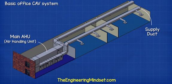
Here we have a simple model of a CAV system for a simple small office. First of all we have the main air handling unit in the mechanical room. Then we have the supply duct. The fresh ambient outdoor air is sucked into the AHU, it is then filtered and heated up or cooled down within the AHU and a fan pushes this out down the ductwork to be distributed throughout the building. Coming off of the main supply duct are a number of branches.
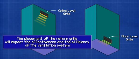
Each branch has a diffuser at the end, the diffuser has metal fins which are at an angle to direct the stream of air and distribute it across the room. This air is then circulated around the room and pushes the dirty used air into the return grille. The return grille is typically on the opposite side of the room, sometimes at floor level, sometimes at ceiling level. The placement of the return grille will impact the effectiveness and the efficiency of the ventilation system. Industry bodies such as ASHREA, CIBSE, BSRIA provide guidance on the design of such system.
By the way you can download a personal copy of video HERE along with a PDF ebook, which you can store on your devices and use whenever you need HERE.
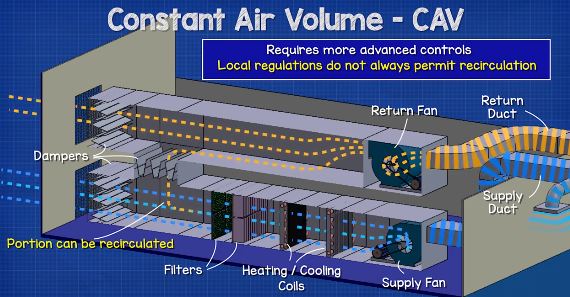
The return grille is connected to the main return duct. This again runs the length of the building and returns to the AHU. A separate return fan pulls the air in through the grille and brings this back to the AHU. This used air can then be rejected from the building, although some designs of AHU allow a portion of this air to be recycled back into the supply. This will reduce the energy consumption of the system. This does require some more advanced controls to determine when conditions are right to recirculate the air, some local regulations do not always permit this system to be used.
CAV System Operation
Now, CAV systems do have some limitations because their supply air temperature is varied but the volume or flow rate of air being supplied is kept constant. So, while the system is operating, it provides air at a consistent and constant volume and only the temperature of that air changes.
Typically, the air is provided at around 13 degrees Celsius, or 55 degrees Fahrenheit, but this can be adjusted to suit the needs of the building. Keep in mind that heating or cooling the air does consume a lot of energy and this increases the operating costs of the building.
As we mentioned, the volume flow rate of the entire system and therefore each room is kept constant. We have to calculate how much air each room will receive during the design phase. That depends on the size of the room as well as the purpose or what’s happening inside each room. For example a server room is going to require much more cooling than a storage room. There are industry guides available which will tell you how to calculate this. Each branch has a mechanical damper which is manually adjusted during commissioning to ensure the correct air flow rate as per design.
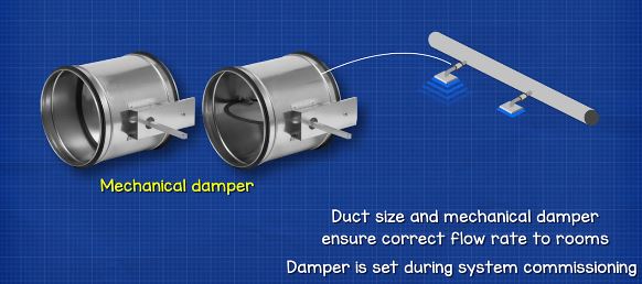
For example, this small room in the centre might require just 3 cubic meters per second or 6356 cubic feet per minute. Where as these two larger rooms on either side might require 20 to 30 cubic meters or 42377 to 63566 cubic feet per second. The size of the ductwork, the damper and obviously the AHU fan will let us achieve that.
The total system flowrate depends on the size of the building. Perhaps a small building only requires a total flow rate of 30 cubic meters per second or 63,566 cubic feet per minute. But it could be an old 40 storey building with an enormous AHU on the roof which is pushing air down through the entire building, that’s obviously going to be an incredible amount of air moving.
Now, one of the main problems with the CAV system, is that everything connected to the AHU and supply duct is classed as one zone. That means all the rooms connected to it receive the same temperature air regardless of their heat load.
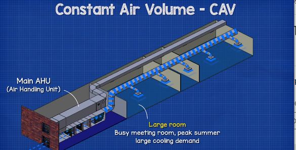
For example, this room here could be a busy meeting room in the middle of summer, so we have a very large cooling demand with all the solar thermal heat gain etc. But this room will receive the same temperature air as this little room which might be a tiny office for one person. That’s going to be very uncomfortable for that person.
This means the rooms are not receiving their required cooling demand, that means the system is very inefficient because we’re generating a lot of cooling which is simple being wasted, because the rooms do not require it.
The AHU fans would also run at 100% the entire time the system is running. Although you could fit a variable frequency drive to the fan motor and slightly reduce the flow rate for periods of low occupancy, although keep in mind this will impact how much fresh air is entering each room. Fitting just a VFD will not convert this system into a variable air volume system, we need a lot more controls, vav terminals etc. It takes a lot of time and money to convert a system but it can be done. It might not be economical to convert a system, it depends on the size of the building and the life span of both the equipment and the building.
We have also covered how AHU’s work in detail in our previous article. Do check that out HERE.
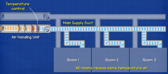
From this schematic representation of the CAV system, you can see how it’s all connected. Notice that all of the rooms are connected to this main duct here, and the only form of temperature control is in the main AHU. That means all these rooms receive the same temperature air at a constant volume. As I mentioned earlier in the video, some AHU’s have the ability to recirculate a portion of the air back into the supply steam, this will save energy but we don’t always find this used or perhaps building regulations do not always allow this.
Coming back to the rooms, the CAV design would work very well if all of the rooms have a similar cooling demand. Say the building was underground or just had minimal solar heat gains, and each of the rooms had a consistent heat load inside them that didn’t vary too much. Then a VAV system would be ideal. Although it is difficult to change the design if the purpose of the room is ever changed. Sometimes we will have multiple CAV systems in a building, to give us that zone control, so each CAV system is providing a different temperature air to suit the zone otherwise every room receives the same temperature air regardless of what’s happening inside the room.
A possible solution to this, is to install terminal reheaters. These are usually found just before the diffuser in the ceiling, and these are typically electrically powered heaters although they could also be from your hot water system. These units will heat the local incoming air up to a higher temperature, to suit the individual room. But obviously that is very energy inefficient because you’re already cooling the air down in the main AHU which costs a lot of money. Then we’re also paying to heat the air back up again to suit the rooms. So we’re wasting energy and money on both cooling and heating.
Typically, the air temperature for this type of system is supplied at the coldest temperature possible to satisfy the room with the largest cooling load. So, for example, this room might have the largest cooling load so the system provides the air temperature to suit this room. These other rooms use reheaters because the air is too cold.
Dual Duct CAV System
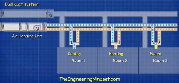
You might come across dual duct CAV systems. It’s very uncommon to see these days but some older buildings still use them. With this system we have two ducts running along and supplying the rooms. One of these will be carrying cold air and the other will be carrying warm air. The air streams are then mixed by some dampers to suit the individual room. The air is then collected in the main return duct and sent back to the AHU to be either rejected to atmosphere or recycled.
Now, this system does provide an improved thermal control, compared to the standard single supply duct CAV system, but there is little control of the humidity. Again, it’s not energy efficient either. As you’re supplying air through two streams, you’ve have high frictional losses in the ductwork which the fan is going to have to overcome. You’re also unnecessarily heating and cooling air.
If you have one of these systems and you want to make it more energy efficient, then you should ensure that a temperature reset is enabled on the system. This will monitor the demand and reduce the hot air stream temperature to the lowest acceptable temperature, meanwhile also increasing the cold air stream to the warmest acceptable temperature. That way we’re minimising our heating and cooling energy demand and thus operating costs.


")

")

Do you have anything on VAV systems?
What are the advantages for headering of primary chilled water pumps in a primary/secondary System?