

Learn about the alternator relay, to understand where and why it is used with simplified examples as well as why engineers install duplicate mechanical plant items such as pumps, fans and compressors.
Scroll to the bottom to watch the YouTube tutorial
Why do we almost always find duplicates of things such as pumps, fans and compressors in building services engineering? Why does only one of these work at a time, why do they sometimes swap over and what controls them. That’s What we’ll be covering in this article which is kindly sponsored by Tele controls, who are one of the leading manufacturers in the automation industry since 1963.
Their load monitors give you peace of mind when it comes to heavy-duty monitoring and utilization of pump systems. They offer protection and optimization to your equipment.
Check out their load monitoring relays, along with suitable relay bases and accessories. You can contact them at [email protected] or via LinkedIn.
To learn more, click HERE
Why is Duplicate Equipment Installed?
In commercial buildings, high rise residential, industrial plants and utilities infrastructure we almost always find duplicates of mechanical plant items such as pumps, fans and compressors.
The simple reason for this is that if one fails, the other can take over.
Take this pump set for example, this supplies water to a storage tank which then supplies each floor. We need to ensure that water is always available.
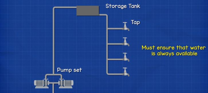
There are two pumps connected to the same pipe, but only one pump runs at a time. The pump which runs is called the duty pump, the idle pump is called the standby pump. So, we have a duty and standby pump set. Depending on how critical the pumping system is, we might even find multiple standby pumps for added safety. This also applies to fans, chillers etc.
Now, if the duty pump was to fail, we need the standby pump to take over. So how do we control the pumps? We need to use alternating relays, and we’ll see how and why we use those a little later in the article.
Another reason for duplicate plant items is load matching.
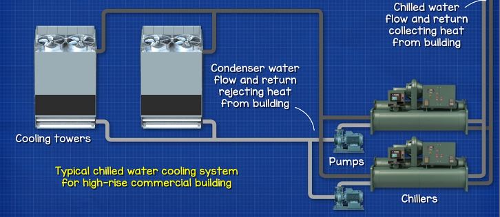
If you imagine a typical office block, it might have 2 sets of chillers to provide cooling. In the middle of summer, when the cooling load is the highest, both chillers and pumps operate. But, in the middle of winter the cooling load is much smaller, so one chiller and pump operate. Therefore, we might need the standby set to also provide support if the duty set can not cope by itself. We can also save a lot of energy by running pumps and fans at the same time, making use of the fan affinity laws but we won’t cover that in this article.
Pump Alternating Relay Example
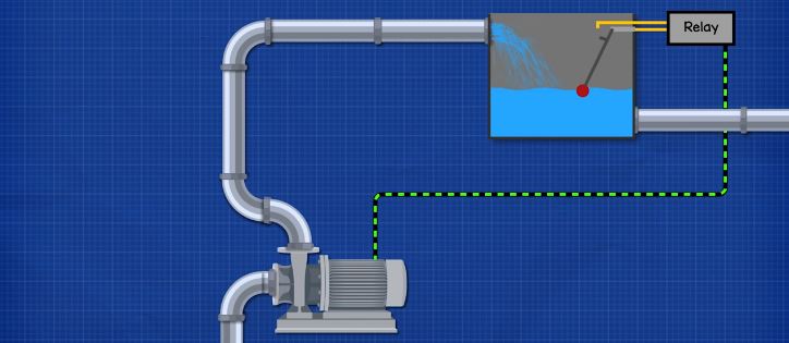
This pump fills a storage tank, it’s controlled by a float switch. When the water level drops too low, the float switch triggers a relay which starts the pump. When the water level is high enough, the relay cuts the power to the pump.
By the way we have covered how relays work in detail in our previous article, check it out HERE.
Now this pump and relay work well. But, if the pump breaks, there is no backup so the entire system is out of service until the pump can be repaired or replaced.
That’s an easy to solve problem, we just install a second pump and control the two with an alternator relay. Now, when the duty pump fails, the relay cuts the power and changes over to the standby pump.
The problem we now face, is that if the standby pump hasn’t operated in a long time, the bearings will have ceased and the internal parts might have rusted so the back up pump will not be able start.
To stop this from happening, we can alternate the control the pumps so that they take turns. The pumps will then have nearly equal run hours and the wear will also be equal.
Alternating Relay Operation
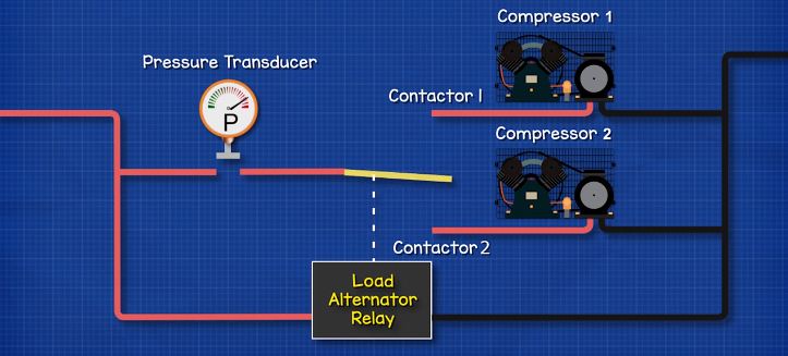
Here we have a simple schematic of an alternating relay circuit, controlling two compressors. The pressure transducer is connected to the common wire of the relay which feeds the compressors. The relay controls a switch which diverts the flow of electricity.
We will look at what happens inside the Alternating Relay a little later in the article.
As the pressure in a compressed air system falls, the pressure transducer closes and completes the circuit. Electricity can then run through contactor 1 and which turns on compressor 1. The Alternating Relay does not energise/operate/change at this point.
When the pressure in the system increases to a satisfactory level, the pressure transducer opens and cuts the power to the compressor. The Alternating Relay then changes position.
When the pressure drops again, the relay is diverting power to compressor 2, and this time compressor 1 is off.
When the system pressure builds up again the transducer opens, Compressor 2 stops and the alternating relay changes back.
Each time the transducer opens, the Alternating Relay flips to the other set of contacts. This ensures that each compressor runs for an equal number of hours and that the wear on the components are the same. The compressors swap from the Duty and Standby role each time they are called to run.
How Does an Alternating Relay Work?
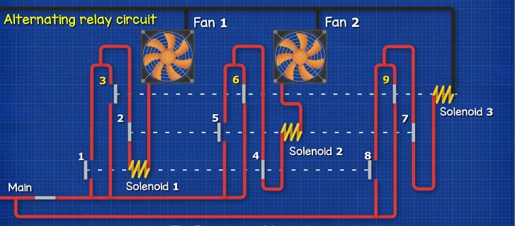
Here we have a diagram of a simplified alternating relay circuit. It might look complex, but don’t worry we’re going to work through it step by step. We have 3 solenoids, and 10 switches. These control the 2 fans and alternate them.
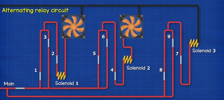
Switch 1 is the main switch that turns the entire circuit on and off. Switches 1, 4 and 8 are interlocked with solenoid 1. Switches 2, 5 and 7 are interlocked with solenoid 2. And switches 3, 6 and 9 are interlocked with solenoid 3.
When current flows through a solenoid it generates a magnetic field, this pulls the connected switches and they change position.
We have covered how solenoids work and even made one in our previous article, do check that out HERE.
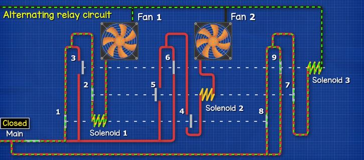
Currently the main switch is open so the fans are off.
Ventilation switched on
When the main switch is closed, current can flow through switches 3 and 2, this energises solenoid 1 and Fan 1 also turns on.
As solenoid 1 has energised, this causes switches 1 and 8 to close and switch 4 opens. The current now flows through switches 8 and 7 and through solenoid 3.
Solenoid 3 energises, this closes switches 9 and 6 and opens switch 3. Fan 1 continues to run as the current now flows through switches 1 and 2.
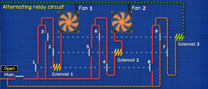
Ventilation switched off.
When the main switch opens, the current stops flowing through switches 1 and 2. Solenoid 1 de-energises and fan 1 stops.
As solenoid 1 has de-energised, switches 8 and 1 open and switch 4 closes. Current still flows through switches 9 and 7 and solenoid 3, which keeps switches 3, 6 and 9 in position.
Ventilation switched on.
When the main switch closes again, and current passes through switches 6 and 4 to solenoid 2, and Fan 2 runs.
As solenoid 2 is energised, switches 2 and 7 open and switch 5 closes.
The current to solenoid 3 is cut, causing switches 9 and 6 to open and switch 3 closes. Fan 2 continues to run
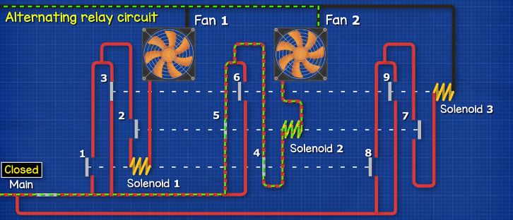
Ventilation switched off
When the fan is no longer required, the main switch opens. This cuts the power to fan 2 and it turns off. There is no current to solenoid 2 so fan 2 stops.
Solenoid 2 is de-energised, causing switches 2 and 7 to close and 5 to open. Both fans are now off.

So that’s how we can switch between loads using solenoid coils and switches. But to make it much easier, we can use an alternating relay to do this for us.
Dual Running at Peak Load
Sometimes we need to run both pumps, fans or compressors at the same time. For example, with a set of air compressors, if the demand for air is very high, then two compressors might need to run to meet the demand. For this we use lead and lag sensors.
The lead sensor detects the initial decrease in pressure and tells the duty compressor to start. If the pressure then continues to decrease, the low-level or lag sensor tells the standby compressor to also start.
Let’s see how this works using a simplified diagram. If it looks confusing don’t worry we’ll go through step by step.
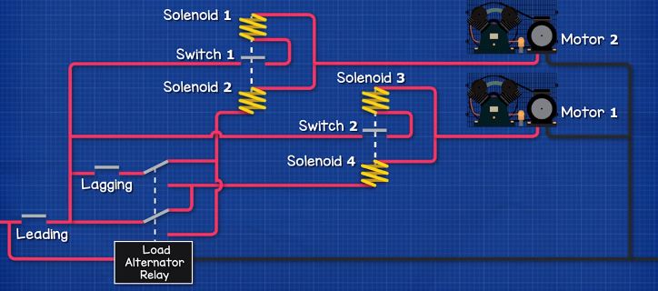
First, we have the lead and lag pressure transducer switches. Then we have two electrical motors for the compressors, but it could also be for a pump or fan etc. We have switches 1 and 2 which are normally open, these are controlled by solenoids 1, 2, 3 and 4 and we also have an alternator relay which controls the interlocked switches.
Initially both Lead and Lag pressure transducers are open and both motors are off. When the lead switch closes, motor 1 turns on.
Solenoid 4 is energised and closes switch 2, this also energises solenoid 3.
If the pressure continues to drop, the lag switch closes and motor 2 also turns on.
Solenoid 2 causes switch 1 to also close, this will then energise solenoid 1.
When the lag transducer is satisfied it opens the switch, but both compressors continue to run.
We want both motors to continue to run, this will ensure the demand for air is satisfied, because we know that one compressor alone wasn’t enough to satisfy the demand. If we didn’t keep both motors running, then the standby motor might continuously turn on and off, this will damage the electrical motor and eventually destroy it.
When the lead switch is satisfied, it opens and both motors turn off. Switches 1 and 2 open and the alternating relay changes position to change the duty and standby over.
Now, when the lead switch is closed, motor 2 turns on. Solenoid 2 closes switch 1 and then solenoid 1 turns on.
When the lag switch closes, motor 1 turns on. Solenoid 4 will close switch 2 which also energises solenoid 3.
When the lag switch opens, solenoid 4 turns off but motor 1 continues to run.
When the lead switch opens, both motors turn off, switches 1 and 2 reset and the alternator relay changes the lead and standby positions.
This is a simplified example to help visualise how it works, but modern alternating relays will use solid state electronics and will have many additional functions such as maintenance override, time on and time off delay features and automatic fault change over.


")

")
