

Essential chiller terminology. In this article we’ll be covering essential chiller terms. These are terms you will hear engineers say when they talk about chillers and they will expect you to understand exactly what they mean.
Scroll to the bottom to watch the YouTube video tutorial
Looking to learn more about chillers and how to achieve optimal chiller efficiency? Then you need to check out what Danfoss has to offer. Danfoss wants to help you build higher-quality, longer-lasting, and more efficient chillers, and they have a wide range of solutions to help make it possible. In fact, they have up to 70% of the products you need for your chiller systems, including compressors, AC drives, system protectors, heat exchangers, valves, electronics, and sensors.
It doesn’t matter what kind of chiller you’re working with — Danfoss has products that can help you boost performance, increase reliability, and reduce the impact on the environment. All of these solutions come together to help you design and create better chillers – from the inside out.
You can get started by heading over to Chillers.Danfoss.com
Refrigeration cycle
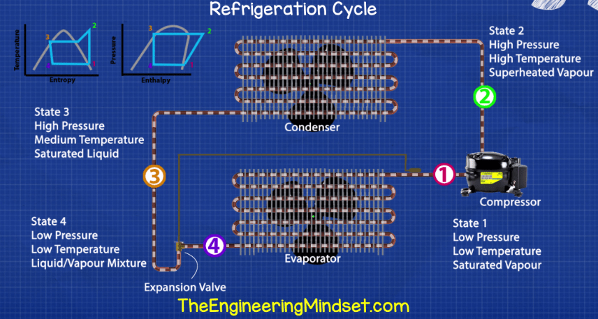
This is the process of how the refrigerant cycles around the chiller, or any refrigeration system. The compressor is the driving forces of the refrigerant. The refrigerant leaves the compressor as a high pressure high temperature gas and moves to the condenser.
The condenser cools the refrigerant and rejects the thermal energy into the atmosphere, the refrigerant leaves the condenser as a high-pressure liquid. The refrigerant then heads to the expansion device which reduces the pressure and the refrigerant becomes a low-pressure liquid/vapour mixture.
The refrigerant then passes through the evaporator where the unwanted heat of the building is added, this boils the refrigerant into a low pressure vapour, as it evaporates it takes with it the unwanted heat which the compressor sucks in to repeat the cycle.
Refrigerant
This is a specially designed fluid which moves around the inside of the chiller collecting unwanted heat from the evaporator and moving this over to the condenser so that this heat can be rejected from the building. It changes states between a liquid and a gas during the refrigeration cycle and It is moved around the inside of the chiller by the compressor. The refrigerant stays within the chiller and is always kept separate from the condenser water and chilled water. The refrigerants will have strange names such as R134A R1233zd etc
Read our previous article on how refrigerants work and how new laws are causing a phase out as well as our guide on how to retrofit older systems with banned refrigerants.
Condenser

This is where the unwanted heat of the building is rejected to the atmosphere either through an air cooled or water cooled condenser. The refrigerant which carries the unwanted heat from the evaporator over to the condenser will enter as a high pressure high temperature gas and as the thermal energy is rejected it will leave as a high-pressure liquid.
Condenser water
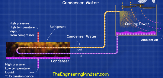
Condenser water is the water that flows between the cooling tower and the condenser of the water-cooled chiller. This picks up all the unwanted heat in the condenser which was transferred over via the refrigerant. It also collects the heat from the compressor in certain designs. The condenser water is sent to the cooling tower where the heat is removed and rejected to atmosphere and it then returns back to the condenser to pick up more heat. A typical temperature would be: Flow: 32°C (89.6°F) Return 27°C (80.6°F) these numbers are typical, they can and vary from this.
Air cooled
This refers to an air-cooled chiller. These are located outside the building usually on the roof or down near the car park etc. Very rarely they are located inside the building but they can be fitted with duct work to achieve this. These types of chiller do not use condenser water circuits. They instead use fans to blow air across the condenser which is why they are called air cooled chillers.
Water cooled
This refers to a type of chiller which uses condenser water and cooling towers to remove the heat from the condenser. These are located inside the building typically in the basement.
Evaporator
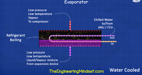
The evaporator is where the unwanted heat of the building is collected before being transferred over to the condenser. As the unwanted heat enters the evaporator it will cause the refrigerant to boil and evaporate, as it evaporates it will carry the heat away to the condenser. The refrigerant enters the evaporator as a low-pressure liquid and as it evaporates it leaves as a low pressure vapour.
Chilled water
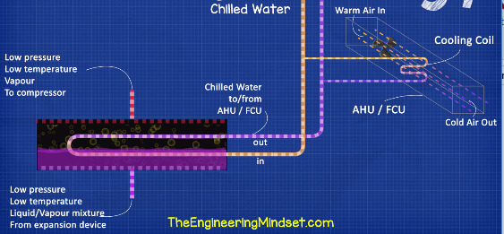
The chiller generates chilled water, this water flows in a closed circuit between the chillers evaporator and the cooling coils within the building. A pump forces the chilled water around the building to the coils within the AHU’s and FCU’s where the unwanted heat in the air will transfer into the water, this cools the air down and warms the “chilled water” up, this warm chilled water then returns to the chiller evaporator to dump this unwanted heat. As the heat is dumped it causes the refrigerant boil and carry’s this heat away which causes the water to cool down again. It then repeats the cycle and collects more heat. Typical temperatures of the chilled water are flow: 6°C (42.8°F) Return: 12°C (53.6°F) These numbers can and will vary from this.
One pass, two pass, three pass
This refers to a water cooled evaporator or condenser and the way the water or refrigerant is piped through the component. In a one pass the fluid will pass straight through but for greater heat transfer the tubes can be looped back one or two times to increase the transfer time and surface area, this will allow more heat to transfer over and increase the heat transfer surface area.
Compressor
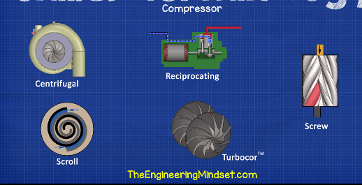
This moves the refrigerant around the chiller to collect the unwanted heat from the evaporator and move it over to the condenser. Some of the different designs you can get for chillers are:
- Centrifugal type which uses a rotating impeller in induce a centrifugal force on the refrigerant which forces it around the system.
- Turbocor type which is a more advanced variation of the centrifugal type, it uses two small rotating impellers to compress the refrigerant
- Screw type which uses two helical rotating screws to squeeze the refrigerant into a tight space and thus compress it.
- Scroll type which uses two spiral discs, one is stationary and one rotates to compress the refrigerant and squeeze it into a small space.
- Reciprocating type which uses pistons and cylinders to compress the refrigerant into a smaller volume.
Cooling Tower
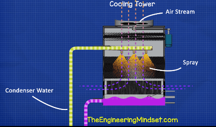
Often refereed to as simply a “tower” these sit on the outside the building, usually on the roof and are only used with water cooled chillers. They are either wet or dry type but both types use fans to move air through the tower. With wet type the condenser water circuit is open and the water is sprayed into the air stream which removes the heat and cools the water down. In a dry type the condenser circuit is closed and the water passes through a heat exchanger where the air stream blows across to remove the heat. Additionally some cooling towers will spray water over the cooling coils to help remove the heat.
Hot gas bypass
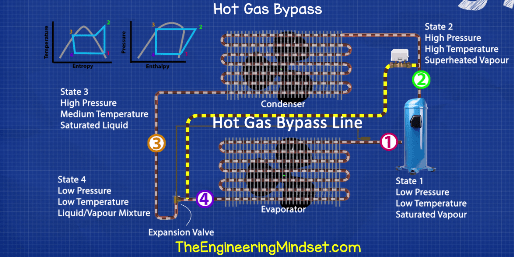
This is only used on some chillers. It is used to create an artificial cooling load to stop the chiller from cycling, stalling, surging as well as protecting the evaporator from freezing under low load conditions. A control valve is used along with a pressure reducing valve to recirculate hot refrigerant from the compressor discharge line and send it straight to the inlet of the evaporator, thus bypassing the condenser so heat is added to the evaporator to create the false load.
This is a pretty inefficient strategy, the energy that went into the compression of the refrigerant will provide no usable cooling effect. If you’re using this strategy then your chiller is likely way oversized.
COP
COP stands for Coefficient of performance. It’s simply the ratio of how much cooling you get per unit of electricity you put in which is a way of measuring the chillers efficiency.
COP = kW of Refrigeration / kW of electricity
2500kW of cooling / 460kW of electricity = COP:5.4 so for every 1kW of electricity you put into the chiller, it will generate 5.4kW of cooling.
The COP varies with the cooling load on the chiller. It is useful for measuring the efficiency at a specific point in time or under specific conditions.
Motor starter (soft starter)
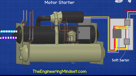
Large chillers, especially those with single compressors such has centrifugal type, can have enormous inrush currents when the motor starts. This means a large flow of power through the buildings electrical system and into the chiller. This can cause damage to the electrical infrastructure and deteriorates the equipment. You might have experienced this when the compressor of a fridge in your house turns on and the lights all dip for a split second. To combat this chillers will use motor starters which limit the inrush of power as the motor starts. These are either built into the compressor, housed in a case on the chiller or are housed in a case nearby the chiller. There are many different methods used to achieve this.
Variable speed drive VFD
Some chillers will use variable speed drives. These effectively do the job of the soft starters but they also control the speed of the compressor to allow it to operate much more efficiently at part load conditions which can lead to large energy savings. They will however result in a reduction in efficiency in full load conditions although chillers typically only operate 1% per year at full load.
VFD’s can also be fitted to pumps to help save energy and allow the pumps to change their flow rate to better match the cooling demand, typically by using a pressure sensor to control the speed.
Rated load amps (RLA)
RLA refers to the maximum amps drawn by the compressor motor during operation. The RLA will vary depending on how much work the compressor has to do. If the RLA is exceeded then the compressor motor will overheat and destroy itself. There are safety features built into the chiller controls to measure this and prevent it. For example a 1272 kW rated centrifugal type water cooled chiller has an RLA of 359 Amps but the chiller will cut the power to the motor if it reaches 455amps. This limit and value varies between all chillers.
Load
Load refers to the cooling demand on the chiller.
Full load means the chiller is operating at its maximum cooling capability, this is only around 1-2% of the year typically.
Part load means the chiller is operating at less than its maximum capability, this is normal for most of the year in typical applications.
Low load means the chiller is operating at very low capacity, faults can often occur at these conditions and chillers typically do not operate efficiently at these conditions. If a chiller is operating at low load for long periods throughout the year then it is oversized and alternative options should be investigated to replace it which will save energy and operating costs.
Cooling load is typically measured in BTU/s refrigeration Tons or kW.
Cooling demand
When the chilled water is pumped from the chillers evaporator around the building to collect the unwanted heat, it returns back at a higher temperature. The amount of water flowing and the temperature will determine the cooling demand. For example a flow rate of 0.0995m3/s with a flow temperature of 6C and a return of 12C will result in a cooling demand of around 2500 kW or 710 RT.
Capacity
This refers to how much cooling the chiller is designed to provide at maximum load. The capacity can be controlled in most chillers so that it closely matches the actual cooling demand at the current time. The capacity is usually stated in units of kW or TR tons of refrigeration.
Relief valves
Relief valves and lines are fitted to chillers to protect the components and operators from a dangerous amount of pressure build up within the chiller from the refrigerant. It is rare that this scenario occurs but it is possible, this might occur for instance in the case of a fire. Typically, the chiller will use a spring-loaded valve which opens automatically if the refrigerant pressure is more than the spring pressure. This will allow the refrigerant to safely vent to atmosphere and the valve will close again once it reaches the lower pressure.
Fouling
This refers to the build-up of dirt and organic substances on the surface of heat exchangers which effectively insulates the surfaces and reduces the heat exchangers ability to transfer heat. This is very common in the condenser of a water cooled chiller because of the open circuit which permits dirt and bacteria to enter the pipework. Good water treatment and monitoring over time should be implemented to reduce this. Chillers are designed to withstand a certain amount of fouling under normal operation but if this is exceeded then the chiller will be unable to reach design capacity.
Lift
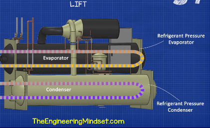
Lift refers to the difference in pressure between the refrigerant in the condenser and the refrigerant in the evaporator. The higher the difference the more work the compressor is having to do in order to achieve this. The chilled and condenser water temperatures and the approach temperatures set the required lift. Reducing the condenser water setpoint and increasing the chilled water setpoint will reduce the energy consumption of the compressor.
Approach temperature

This refers to the temperature difference between the chilled water supply temperature as it exits the chiller compared to the temperature of the refrigerant within the evaporator.
For example the chilled water supply temperature might be 7°c (44.6°F) and the refrigerant might be at 3°C (37.4°F) Approach therefore equals 4°C or 7.2°F. A difference 3-5°C or 5-8°F is typical.
Setpoint, active chilled water setpoint
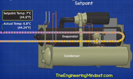
Setpoints within chillers refer to a desired temperature or pressure, usually this has a focus on the chilled water supply temperature. The desired temperature is defined within the controls and the chiller tries to meet this temperature. A temperature sensors at or near to the chilled water supply outlet of the evaporator will measure the actual temperature and the chillers controls will make adjustments to meet this or operate as close as possible to it.
Chilled water pump and condenser water pump
These are the pumps which distribute the chilled and condenser water around the building between the chiller, cooling coils and cooling tower. They can be either constant or variable flow depending on the design of the system. Variable flow is increasingly popular in secondary side systems as it can provide significant reduction in energy and operating costs.
Flow rate
This is referring to the quantity of water passing through the chiller or a specific part of the distribution pipework. It’s a measurement of volume per unit of time. Example a gallon per minute (gpm) a litre per second (l/s) or cubic meter per second (m3/s).
Mass flow rate
This is referring to the mass of water flowing through a chiller, pump or a specific point in the distribution pipework. It’s a measurement of weight per unit of time. Example lb/m or kg/s.
Flow meter
A flow meter can be installed on chillers or chilled water systems to monitor the flow to and from each chiller or to measure the flow through the decoupler pipe to diagnose problems as well as ensure efficient operation and signal a second chiller to start or stop. These are often clamp on meters that use ultrasonic sensors to calculate the flow.
Chiller tripped
This refers to the chiller turning off by itself, through the internal controls, due to a detected fault or if it has reached the limits of a design setpoint. E.g. a high or low pressure or temperature. The chiller therefor turns off to protect itself from damage.
Coils
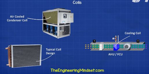
Coils refers to a heat exchanger. There are a few coils in a chiller and chilled water system. A cooling coil would mean the heat exchanger in an air handling unit or fan coil unit which receives the chilled water and exchanges its coolth into the air. A condenser coil would refer to the condenser of an air cooled chiller which receives the hot high pressure refrigerant and uses the ambient air to condense this into a liquid.
Delta T or ∆T
This refers to the temperature difference between the flow and return temperatures of either the chilled and condenser water. A typical temperature difference between the chilled water flow and return would be 6C but this can vary. A high delta T means a chiller is working hard and the efficiency should be high where as a low delta T means the chiller is likely operating inefficiently and there is likely design issued in the cooling system causing this.
Superheat
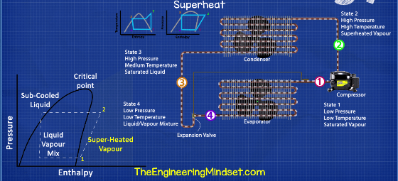
This refers to the number of degrees (Kelvin) the refrigerant is above the boiling point at a particular pressure. A reading of 4-8K is typical. If the reading is high then the evaporator is not operating efficiently and if it is low or zero then there is a fault and its possible that liquid refrigerant can reach the compressor which will cause serve damage.
Subcooling
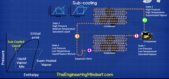
Refers to a refrigerant which has been condensed and is at a temperature lower than its boiling point so it is therefore in a liquid state. It is the difference between the refrigerants saturation temperature and the actual temperature of the liquid refrigerant.
Expansion valve / Device
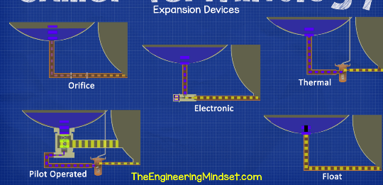
This is a device used between the condenser and the evaporator. These cause a pressure reduction in the refrigerant as well as controlling the amount of refrigerant entering the evaporator which is used to control the superheat. There are many different types used in chillers. Some examples of chiller expansion valves and devices are
- Orifice plate
- Float valves
- Thermal expansion valve
- Electronic expansion valves
- Pilot operated thermal expansion valves
Chilled water reset
This is a control strategy used to save energy. The strategy raises the chilled water supply temperature to reduce the lift which will reduce the amount of work done by the compressor. This will also result in a higher return water temperature which can lead to increased pump speeds in variable speed systems. It can also lead to low delta T syndrome and needs to be carefully analysed before implemented.
Lead and lag or duty and standby
The lead or duty refers to the chiller or pump which is designated to be the first to turn on and handle the cooling load when a building utilises multiple chillers. The lag or standby refers to the next chiller or pump that will turn on if the lead/duty is either unable to handle the full load or if the lead/duty chiller/pump shuts down due to a fault. The lag/standby will either join to provide more capacity or it will take over from the lead/duty. The designation of lead/lag or duty/standby will usually rotate to ensure equal run hours on all the equipment or it will be designated according to the most efficient equipment running at the current operating conditions.
Load profile
This is the cooling demand of the building plotted onto a chart showing the variation usually per hour covering 24 hours in total. The 24 hours can be for either a specific day or it can be averaged over a period of time for example season demand, or the total for a specific year or perhaps each weekday. This is very useful for engineers to analyse, and can allow better control strategies, energy efficiency and energy forecasting.
Package chiller
This refers to chillers which come from the manufacturer in one complete bundle with all the major refrigeration cycle components in one package. This is the most common type of chiller. They can include water or air cooled design
Chiller Economizer
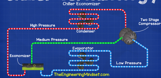
An economizer is used in some centrifugal type chillers with two stage compressors to reduce energy consumption. The design is fairly simple with a special tank placed between the condenser and the evaporator. The refrigerant is partly throttled into the tank and any refrigerant which vaporises in sent straight to the second stage of the compressor. The rest of the refrigerant which is as liquid state will continue to the evaporator. This reduces the work requirement by the compressor and thus saves energy.
Decoupler
This is common in primary secondary systems. It is a pipe placed at the end of a set of parallel connected chillers to hydraulically separate the primary and secondary sides and allows the secondary side to be variable flow. The chillers on the primary side will need to have a minimum flow rate to prevent damage, the decoupler allows chilled supply or return water to flow in either direction to satisfy the primary and the secondary loop pumps. The flow rate through the decoupler will also determine whether a second chiller can be turned on or turned off.
Free Cooling
This refers to a cooling control strategy which rejects heat without or with minimal use of the compressor. This strategy can only be used in certain ambient conditions, it can be enabled when the outdoor air temperature is below the setpoint temperature. Some chillers have this function built in others can be retrofitted or the system can be modified to accommodate this.
")
")


")

")

I find your information very useful for what I am looking for.
Thsnks