

Neutral, Ground and Hot wires explained. In this article we’re going to be looking at the difference between hot, neutral and ground wires as well as the function of each with some examples. This topic is for homes in north America. If you’re outside this region then you can still follow along but your system will work and look different to this so check our other topics.
Scroll to the bottom to watch the YouTube tutorial on Ground, Neutral and Hot wires.
Warning
Remember electricity is dangerous and can be fatal. You should be qualified and competent to carry out any electrical work. Never work on live/hot electrical circuits.
Before we get into this video there are three things I need you to remember.
1) Electricity will only flow in a complete circuit, if you come into contact with an electrical conductor, your body might complete the circuit.
2) Electricity always tries to return to its source.
3) Electricity takes all available paths to complete a circuit. It takes preference to a path with less resistance and more current will flow in that path.
We’re going to be looking at the hot, neutral and ground wires for a typical north American residential electrical circuit. But first we will see a really simple circuit to understand how it works, then apply this knowledge to a complex residential installation.
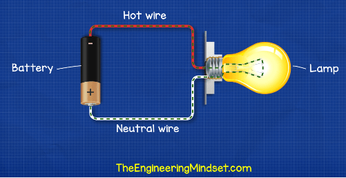
When we look at a simple electrical circuit with just a battery and a lamp. We know that to turn the lamp on we need to connect both ends of the wires to the terminals of the battery. Once we connect these wires, the circuit is now complete and electrons can flow from the negative, through the lamp and back to the positive terminal.
Electrons flow from Negative to Positive. This is called Electron flow. Originally it was believed they flowed from Positive to Negative. This was later found to be incorrect and we call this Conventional Current.
So for the circuit to be complete we need a wire to carry the electrons from the power supply and to the light, this is our hot wire. Then we need to connect from the lamp and back to the battery for the electrons to get back to their power supply, or their source. This is our neutral wire. The hot wire carries the electricity from the power supply to the load and the neutral wire carries the used electricity back to the power supply.
Current loading on circuits
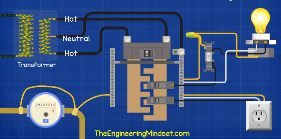
If we look at a residential electrical system in north America then we will find two hot wires, a neutral wire and some ground wires. If you want to see how this works in detail, then we have a tutorial video for that click here to see.
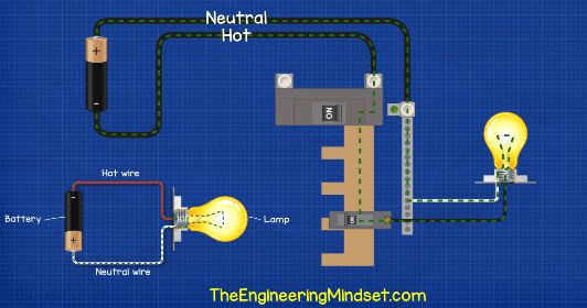
Imagine for a second that the homes electrical system is connected to a battery and we have just one hot wire and a neutral wire. As we saw with the simple circuit, for the light to turn on we need a hot wire to supply the current to he load, and we need a neutral wire to return the current to the source. Electricity therefore flows through the hot, through the bus bar and circuit breaker and into the light. It then travels back through the neutral and to the source.
Of course homes aren’t connected to batteries they’re connected to transformers. So we replace the battery with a transformer, and we have a complete circuit.
The electricity in this circuit is AC alternating current, which is different from the DC direct current we saw with the battery. With DC the electrons flow directly from A to B in one direction much like the flow of water down a river. But in our homes we have AC alternating current which means the electrons alternate their direction between forwards and backwards much like the tide of the sea.
Now in north America we have a split phase supply to most residential properties, so we have the two hot wires and one neutral wire. We simply have two 120V coils connected together in the transformer, the neutral is then connected to the centre between the two coils.
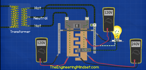
When we connect our multimeter between a hot and the neutral we get 120V, and we get the same reading for the other, that’s because we’re only using half the coil in the transformer. When we connect between the two hots we get 240V because we’re using the full transformer coil.


If you don’t have a multimeter I highly encourage you to get one, it’s an essential tool for any find finding and electrical work.
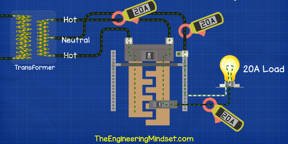
If we have a load on only one half of the coil, between the hot and the neutral, and the load is for example 20A, then the hot will carry 20A to the load, and the neutral will carry 20A back to the source.


We can measure the current in a cable using a current clamp meter.
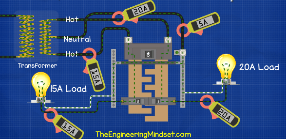
If we have another load on our other half of the coil, between the other hot and neutral, and the load is a different value say for example 15Amp, then the neutral will only carry the difference between these two values back to the transformer. In this case 20A – 15A = 5A so the neutral will carry 5A back. The rest of it will pass through the two hot wires. This is what we will have in most cases because there are multiple circuits all with different loads.
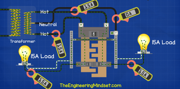
If we had a load on both coils and they are of equal value, say for example 15A each, then there will be no current flowing in the neutral wire. It’s all flowing back and forth on the two hot wires between the loads and the source. That’s because it’s AC alternating current and the transformer is centre tapped with a neutral, so while one half is moving forwards, the other half is moving backwards and the current will flow into the other circuit instead of back via the neutral.
For detail animations, check the YouTube video below
The hot wires carry the electrical current from the supply and to the load and the neutral wires carry the electrical current from the load and back to the supply.
What does the ground wire do?
The ground wire under normal operating conditions will not carry any electrical current. This wire will only carry an electrical current in the event of a ground fault. Hopefully this wire will otherwise never be used at all for it’s entire life. It’s just there as an emergency path for the electricity to get back to the power source instead of it passing through you. The ground wire in most cases is a bare copper wire, it’s uninsulated, but it is sometimes covered with a green insulation. This wire has a very low resistance so electricity will prefer to travel along it because it’s easier and can get back quicker.
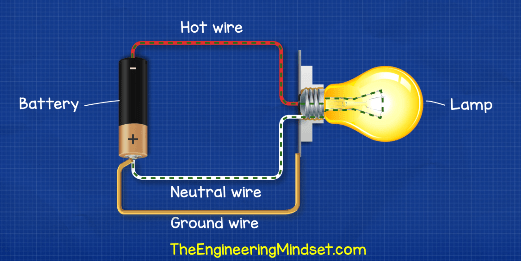
Going back to the simple circuit with a battery and lamp. If we now take another wire and run this from the positive terminal over to the lamp and connect it to the metal lamp holder, this is effectively our ground wire. It’s not being used to carry electricity. If the hot wire touches the metal casing, then the electricity will now flow through the ground wire instead. If the hot wire comes into contact with both the neutral and the ground, then it will flow through both wires back to the source but as the ground has less resistance more current will flow through it.
When electricity finds a way to leave its circuit and return to the source through a different way than it’s neutral wire, we call this a ground fault.
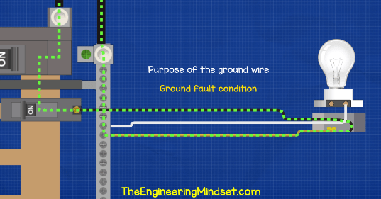
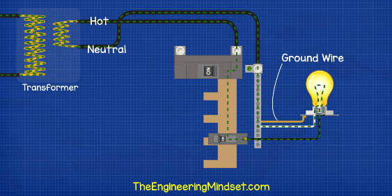
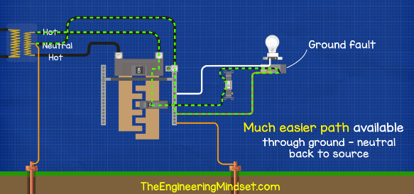
Coming back to the house, the electricity flows through the hot and the light and back through the neutral. But if the hot touches the metal casing then it will instead flow through the ground wire back to the panel, then through the bus bar and then back to the transformer via the neutral wire. The ground wire has a very low resistance so it causes a huge and instantaneous increase in current which will trip the breaker.
We therefore connect ground wires to anything that could potentially become a potential path for electricity to leave it’s circuit such as the metal pipes, the metal plates of the light switches and outlets and their boxes. We also need to run one to the outlets because often our appliances will have metal casing, like washing machines and microwaves.
When you look at a receptacle and plug you’ll see there is a hot terminal, a neutral terminal and a ground terminal. The casing of something like a washing machine is connected to a ground wire in the lead which goes to the plug, through the receptacle and back to the panel to save you from an electric shock.
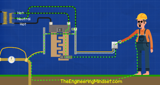
Now lets say you’re outside with no shoes on and the ground is moist. If you touch a hot wire, you will complete the circuit and the current will pass through you to get back to the supply. In this case, the resistance is very high so the current might not be high enough to automatically flip the breaker and cut the power. This will likely lead to the persons death.
Luckily we have the GFCI receptacle or GFCI breaker. GFCI stands for Ground Fault Circuit Interrupter. We’ll look at the circuit breaker version but they essentially work the same.

This GFCI breaker is going to be connected to both the hot and the neutral of the circuit so it can monitor the wires and ensure that the current running in the hot wire of the circuit is equal to the current in the neutral wire of the circuit. If the current is not equal then it is clearly flowing back to the source via another route, for example via a metal pipe, so we have a ground fault. The breaker will realise this very quickly and automatically flip to cut the power to the circuit.
Ground rod
Connected to the main panel we will find a thick copper wire which leads to a ground rod. The ground road is buried into the ground outside near the property. This rod is not used for ground faults. It’s purpose is to dissipate static electricity and high external voltages like lightening strikes.
There is also a ground rod connected to the neutral at the transformer. Many people think that during a ground fault, electricity flows through their ground rod and into the earth. But remember electricity tries to get back to it’s source. As there is a ground rod at the transformer there is a potential path for the electricity to get back to the source. BUT, this path will have a very high resistance, or impedance as this is AC, and as we know electricity will take preference over the path with least resistance. As we already have a low resistance ground wire which provides a path directly back to the source, the ground fault is going to take this route instead.
When it comes to lightening, the source of lighting is essentially the earth. So lightening is trying to get back to it’s source which is the earth. If lightening strikes the utility cables it will flow along the wires to get to the ground rods of both the transformer and the main panel, to get back to the earth. Otherwise it’s going to blow all our circuits and cause fires.
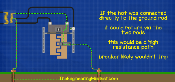
If the hot wire came into direct contact with the ground rod, then electricity will flow through the soil back to the transformer but the resistance is very high so the current will be low. This means the circuit breaker will be unlikely to detect this fault and the breaker will not automatically flip to cut the power.


")


")

")
There was a neutral wire cut or disconnection at a distribution transformer supplying me with electricity and I think it led to very high voltage which damaged my phone plus it’s charger and electric bulbs.
So please can you explain to me without using technical terms, what’s the function of a neutral wire at a distribution transformer and what happens if the neutral wire gets cut or disconnected at the transformer? Can the neutral wire disconnection led to excessive and dangerous voltage? What can cause the neutral to be disconnected or cut at the distribution transformer?
So on that last slide where the hot wire is connected directly to the ground, wouldnt the current take the path of least resistance and go back to the source through the neutral instead of the ground at the breaker box, thus tripping the breaker? If not why?
What neutral? The hot is connected directly to the ground rod. Visually it looks like it may connect to the neutral bar, but it’s just passing over it. There is no second neutral wire. It is a hot wire going to the ground rod.
Your Video was awesome. Thanks for transcripts.
Who is supposed to reply and comment? Let me try, although I am not an electrical engineer or even an electrician. With respect to Timothy’s question. Simply put, you want 120 Volts at the outlet in your home. 120 Volts is between the hot/live wire(s) and the neutral wire. Between the two live wires we have 240 Volts. When the neutral is disconnected, 240 Volts remain, which is too much for a 120 Volt appliance.
I first saw the video yesterday (and didn’t notice the text version/transcript). And although the comments are positive, I think it could be more precise. The battery example calls the wire to the positive pole of the battery ‘neutral wire’ and says that this is the wire through which the (used) electricty flows back to the source. But this is DC, with AC the direction of the current changes 60 times per second. We don’t have live and neutral wires changing 60 times per second! I find it confusing anyway to talk about ‘used electricity’ and ‘flowing back’. It makes it more complicated than it is.
Simply, the neutral wire is called so by convention. And this is because its potential (the voltage) relative to earth (the ground on which you are standing) is kept at zero or at least as low as possible. This means. that – when there is no fault in the system (so other than in Timothy’s case) – you won’t get an electric shock when touching the neutral wire. The potential of the live wires is kept at 120 Volts relative to the neutral wire. That is why there wil flow a current and that is why you will get an electric shock if you touch it: the current wil flow through your body between the earth and the live wire. Remember: the earth is at the same potential as the neutral wire.
And then, as far as I understand it, there is grounding and there is earthing. The purpose of grounding is to prevent parts of electrical appliances and other installations that might come into contact with electricity that are able to conduct electricty and that you can touch, to have a potential that can be dangerous, for example as a result of an internal fault. Grounding is done through connecting these parts with the ground wire to a point that is at zero potential. This might be an earth rod or web, and then it is called earthing.
please explane too me what hot’s mean in amercian electric?
Can you tell me how to add a new neutral wire, i’m trying to do an wifi switch and it requires a neutral, currently the switch box does not have a neutral
I enjoy your videos and they are very informative for people that don’t work with electricity on a regular basis. Your explanations are usually spot-on, but at 6.i5 of the video on the explanation of Ground, Neutral and Hot you go astray. Not sure why, but your description of the “ground” wire is just plain wrong! The “ground” wire is made of the same material as the neutral and hot wires, usually just electrical grade copper. The ground wire isn’t made of some super-conducting copper (a neat trick if true) but it is thinner so has MORE resistance than either the hot (black) or neutral (white) wires. If your hot and neutral wires are, say, #14 then the solid copper ground wire is going to be #16 or #18, as it has no need to carry vast amounts of current for any prolonged period of time. The difference is that the neutral wire goes to the load and doesn’t (normally) touch the case at all. So normally the ground wire carries no current unless in the rare case when the hot wire shorts out to the case. In that case the neutral wire isn’t a factor as it will draw much less current, as a large amount of “instantaneous” current will go from the hot wire to the ground wire. This will cause the breaker to trip way before the smaller ground wire heats up enough to cause damage. Not sure where you came up with this “low resistance” wire theory, but please redo that portion of your video so people won’t get the you have invented a “low resistance” super-wire. Please let me know when this video is updated.
Thanks, Don
There is some confusion over the wording of this section. The path is directly back to the transformer via a copper wire which is an easier route than through the physical earth. We do not suggest it is made from a super conducting version of copper. We’ll revamp this section in a future video.
First of all congratulations for the excellent content of your channel!
I have a question (from a layman) about an issue that I still haven’t understood…
Current only flows through a closed circuit, right?
In a residential installation we have the phase and neutral coming from the transformer, thus forming a closed circuit.
But what about the generation network (electricity network)?
After generation, 3 phases are distributed over the grid lines. But is there a neutral returning to the generator?
Where do the electrons pushed by the generator as a current come from?
The three phase distribution doesn’t require a neutral, see our three phase tutorials for more information, but as one phase is always in reverse, the current can flow back through there.
In addition to the previous question about closed circuits…
When we have a 127 V circuit (with phase and neutral) current “flows” through the phase wire and “returns” through the neutral wire.
But how about a 220V connection, where two phases “reach” a point?
How is the circuit closed in this case?
Why does alternating current have a hot and a neutral? At one point in the AC cycle the emf is pushing in one direction and the current flows that way. One half-cycle later the emf is pushing in the other direction and the current now flows in that direction for the length of a half-cycle. It seems that which conductor is ‘hot’ alternates back and forth, so why is AC depicted as having one conductor always hot and the other always neutral? What am I missing?
[…] LEARN MORE HERE: https://theengineeringmindset.com/ground-neutral-and-hot-wires-us-can/ […]
[…] https://theengineeringmindset.com/ground-neutral-and-hot-wires-us-can/ […]
[…] We’ve covered Ground, Hot and Neutral Wires in our previous article, you can view that HERE. […]