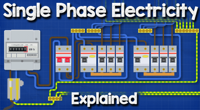
Single phase electricity. In this tutorial we’re going to be looking at a typical single phase electricity supply into a domestic property. We’re going to look at the distribution cables and transformer, the phase, neutral and earth. the Main fuse, the Electricity meter, the Isolation switch, the Consumer unit as well as RCD’s and MCB’s.
Scroll to the bottom to watch the YouTube tutorial on single phase electricity.
Single phase supply is a common design used across the UK, Europe, India, Australia, New Zealand etc, there are some slight variations and the components may look a little different between countries but it’s essentially very similar.
However, North America is a little different because they use two voltages (120/240V) in the home so we’re going to look at that in detail in a separate tutorial, you can still follow along and understand the basics though.
I’m going to be using the European colour codes for this video, that may be different to your local regulations. Remember electricity is dangerous and can be fatal, you should be qualified and competent to carry out electrical work.
The electricity is generated far away at the power station, it leaves the power station and the voltage is increased in a step up transformer where it will then be distributed over long distance transmission lines. We generate and distribute AC alternating current because it is more cost effective and convenient than DC Direct current. Once it reaches the town the voltage will be reduced in a substation step down transformer. If you want to learn how transformers work, we’ve covered that in this article here.
From the substation, the electricity will either be distributed locally through overhead or underground cables.
Depending on the local design and the voltages being used, a home might be connected directly to a small transformer located close to the property, or alternatively, a group of houses will share a larger transformer.
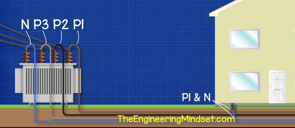
The electricity is distributed in three phases but in this case we’re looking at a single phase installation which means the property is connected to just one of the three phases and the neutral.
How does three phase electricity work? Find out here
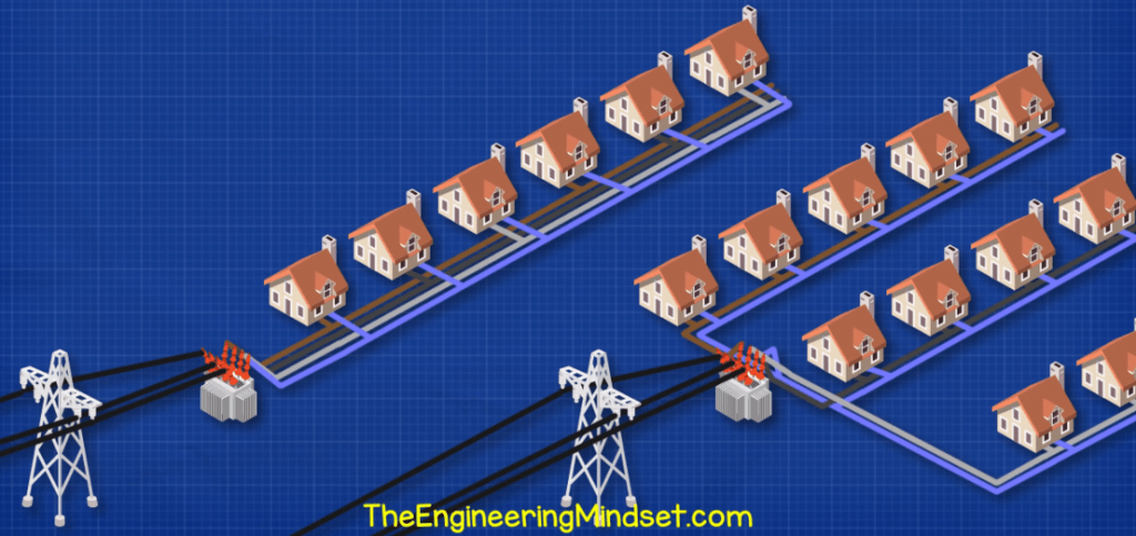
Each house in a street might be alternately connected to a different phase or different streets might be connected to different phases. This is just to try and balance the demand on the transformer.
A smaller service cable comes off the distribution cable and will feed the property. This service cable will again be overhead or underground depending on the local installation.
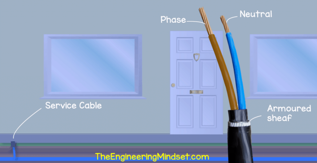
The service cable contains the phase and neutral wires, there’s also a metal protective sheath around the cable in most cases especially if it’s buried in the ground.
The service cable comes in, the phase and neutral pass through the service head, into the meter and then into the consumer unit.
The electricity is going to flow from the phase, pass through the main fuse, then through the meter and into the consumer unit.

The service head or cut out holds the main fuse or service fuse. This fuse provides protection to the property and ensures only a set amount of current can flow into the property. For example in the UK it’s typical to have a fuse rated between 60 and 100 amps. The electricity distribution company may also remove this fuse to isolate the property and will do so for example to replace the meter. Usually this fuse and the service head is owned by the electricity company and it is not allowed to be removed or replaced by the property owner.
The phase and neutral then enter the electricity meter which quantifies how much energy is being consumed. In older properties this meter might be mechanical or digital or even a digital smart meter. There are a lot of variations in design for these.
The phase and neutral will then leave the electricity meter and enter the consumer unit or fuse board. This varies in size depending on the size of the property and how many circuit there are.
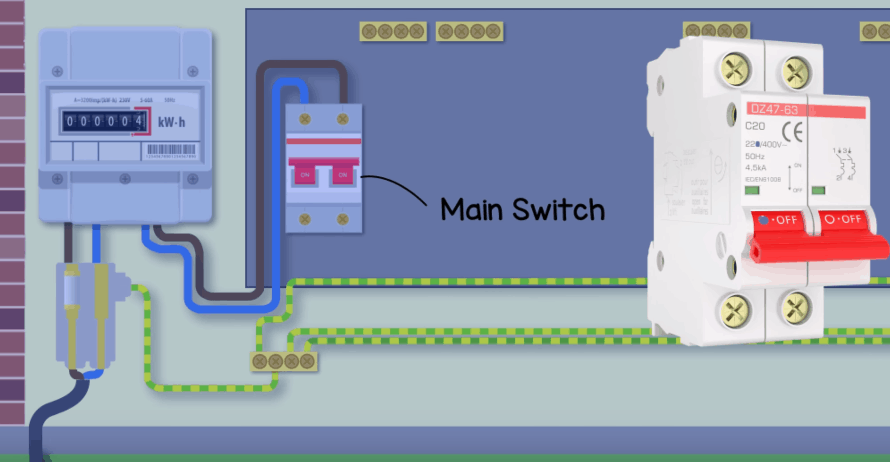
Inside the consumer unit we first have the main switch or main double pole switch. This controls the supply of electricity to the rest of the consumer unit and all its circuits feeding the property. This switch is manually flipped to cut the power. This switch disconnects both the phase and the neutral at the same time. The cables typically enter the main switch via the top terminals. At the bottom we find the neutral wire which connects to a neutral block. We might find one or more phase wires coming out of the bottom of the main switch to feed the RCD’s, if there aren’t RCD’s used then a bus bar will feed the circuit breakers and we’ll look at that shortly.
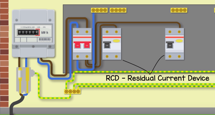
The phase enters the RCD or residual current device, again usually entering via the top. This RCD switch is constantly monitoring the electrical current. It’s checking if the current in the phase line is equal to the current in the neutral line, if it isn’t then there is an electrical fault and the device will quickly and automatically cut the power to everything past the switch. Typically an RCD will break the circuit if it measures a difference of 30 milli amps as anything above this is dangerous for humans. For example, if you touch a live wire and the electricity flows through you to ground then the current is bypassing the neutral wire so the phase and neutral currents will not be equal and the RCD will cut the circuit to reduce the risk of electric shock or death.
It’s now increasingly common to have two or more RCD’s in the consumer unit. In such case the RCD will only cut the power to the circuits connected directly after it, so the other RCD will still be powered and only some parts of the property will loose power. The RCD will trip when it believes the current is unsafe even for a fraction of a second. It needs to be manually reset to restore power, but you should locate and remove the faulty appliance or fixture first.
From the bottom of the RCD we have a bus bar. This is just some conductive metal which the electricity flows along and connects into each of the MCB’s which just makes the installation easier than having lots of cables.
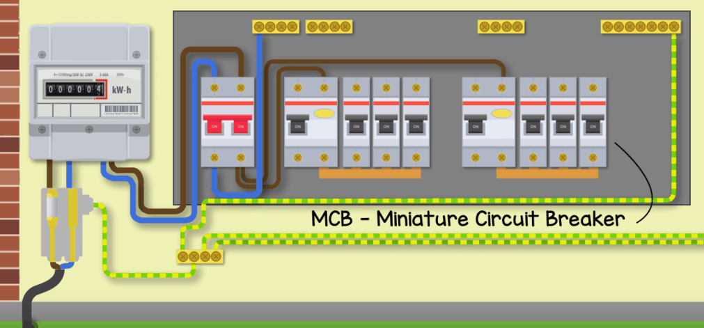
The MCB or miniature circuit breaker controls individual smaller circuits. For example connected to one RCD maybe we’ll have one MCB for the downstairs lighting, another for upstairs lighting and one for the kitchen plug sockets. On the other RCD maybe we have one for the stair well lighting, one for the upstairs lighting and one for the downstairs plug sockets. These switches will quickly and automatically trip to cut the power but need to be manually reset to restore power.
The MCB protects the circuits in two ways, overload and short circuits. The MCB is rated to handle a certain amount of current passing through it, for example 32Amps for the plug sockets. If this value is exceeded on that circuit, for example by gradually plugging too many things in, then the MCB will trip and cut the power to protect itself.
The other protection it offers is short circuit protection. In the event of a short circuit, for example the live touches the neutral, then the circuit is bypassed and there will be a large and instantaneous increase in current. This will create a magnetic field inside the MCB which will cut the power to protect itself.
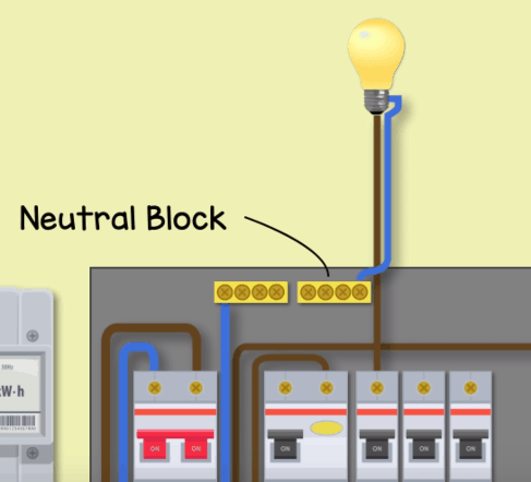
The phase leaves via the top of the MCB and will flow through the circuit for example through some lamps. It then returns via a neutral cable and into a neutral block. All the circuits do this with the phase coming out of the circuit breaker and heading off around the property and the neutral lines coming back and meeting at the neutral block.
The neutral block is then connected to the RCD which checks if the current flowing out is equal to the current flowing back in.
The neutral then flows from the RCD to the main neutral block and from there back to the main switch which is connected to the electricity meter and the service head.
So electricity can then flow from the main distribution phase line, up through the service head and main fuse. It then flows through the electricity meter and into the consumer unit main switch.
From the main switch it flows through the RCD, along the bus bar and into the MCB’s
It then flows up around the MCB’s separated circuits. The electricity can then come back via the neutral wires to the neutral blocks, it then flows through the RCD and into the main block, back into the main switch then the electricity meter, then through the service head and fuse and back into the neutral line of the main distribution cables.
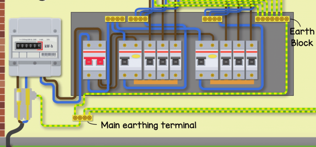
You may have noticed that there’s some other cables with green and yellow stripes. These are called the earth cables.
This earth cable usually runs along with the phase and neutral wires into the fixtures such as light switches and plug sockets. Some appliances will also use an earth wire for added protection typically if the device uses a metal casing. The earth wires will connect from these fixtures into a neutral block within the consumer unit.
All the earth cables for each circuit then connect into the earthing block in the unit.
Another earth cable will then connect from this earthing block in the consumer unit over to a main protective earthing terminal which is typically located near the electricity meter.
Other earthing wires will connect from this main earthing terminal over and onto metal pipes such as the plumbing and gas pipework.
That way if a person touches a live wire and a metal pipe in the property, the electricity will flow through the earth wire and should be detected by the RCD which will cut the power.
There are a few ways the main protective earthing terminal is connected to ground.

The first option is as shown here with the main earth terminal being connected to the neutral wire of the service cable within the service head. This means that the phase to earth fault is effectively now a phase to neutral fault instead.

Another option is to use the metal protection sheaf around the service cable as the earth conductor, so the main earth terminal is connected to the metal sheaf and this carry’s the phase to earth fault back to the transformer.
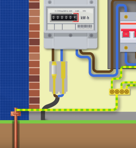
The other option is that the electricity supplier doesn’t provide an earth path
and instead the main earth terminal is connected to an electrode rod which is
installed into the ground and provides a direct earth path.





[…] This system is used in north America so we’ll use their terminology and colour coding. If you’re from outside this region then you can still follow along but your electrical system works differently, we’ve covered this in a separate tutorial, do check that out here. […]
Excellent explanation.
I wish I read something like this 20 years ago.
10/10 Great information
[…] Single phase electricity explained. In this video we learn electrical engineering basics by learning single phase meter wiring diagram. How electricity reaches our homes from the power station, transformer, transmission lines, distribution cables, service head and main fuse, electricity meter, main isolation switch, residual current device and circuit breaker. Electricity basics, how electricity works. LEARN MORE HERE: https://theengineeringmindset.com/single-phase-electricity-circuit/ […]