

In this article we explain how a simple Joule Thief circuit boosts low voltage using inductors, transistors, and Faraday’s law. Learn how it works, why it works, and how to build one yourself with a DIY kit or custom PCB. Learn how transistors, inductors, toroid transformers, LED and resistors work.
Scroll to the bottom to watch the YouTube tutorial.
This battery is dead.
The internal chemical reaction is failing. Normally we would dispose of it. But, watch this.
It can somehow power this white LED. but these need over 3 volts just to turn on. and this dead battery can’t provide anything near that. So, how can that be possible?
The answer lies in this clever little circuit. Made from just a few parts, and uses Michael Faraday’s discoveries from nearly 200 years ago.
In this article, I’ll show you how it works, why it works and also how to build one yourself.
We even have a DIY kit for you to build one at home with all the components included, and if you already have the parts, our sponsor PCBWAY can provide just the PCB’s. More about that later.
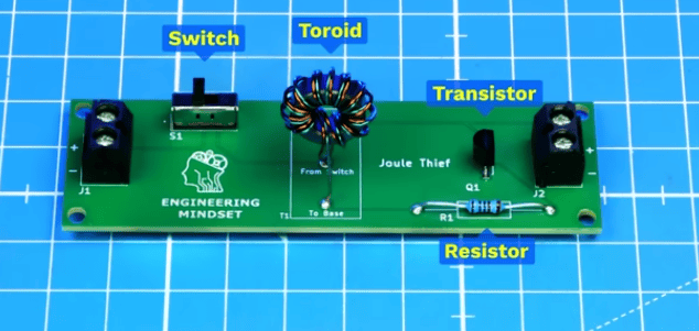
Basically this circuit uses just a switch, a toroid, a resistor and a transistor.
We supply the power into this terminal block and we output power through this terminal. That’s where our LED is connected.
All these components are connected via these traces in the circuit board.
But, I’m going to use this circuit diagram to explain the circuit just because it’s easier to visualise.
When the switch is closed, the circuit is complete so current can flow. But, where will it go?
Well, assuming conventional current, it would flow from the batteries positive, through the switch and then it reaches a junction, with two possible paths to choose from.
Path A runs through this wire through the toroid and reaches the transistor, but, initially, the transistor will block this path. I’ll explain why in just a moment. It could also take this path to the LED, but initially this is also blocking the path because the voltage is too low. So it can’t take this route.
Path B, runs through a different wire in the toroid, this is in the opposite direction, then it passes through a resistor and then it reaches another terminal on the transistor.
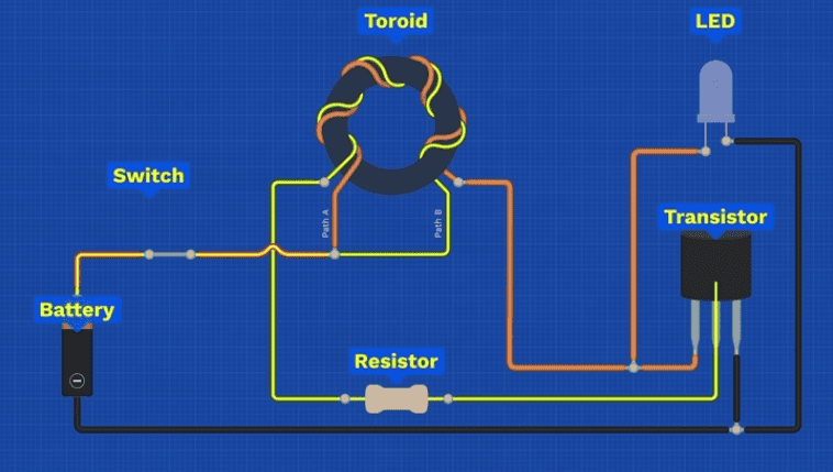
But, this terminal will allow some current to pass through, to ground. So we have a complete circuit here and a small current will flow through this path.
This will start a chain of events between the coils, which eventually lights up the LED.
So we have our circuit laid out, next we need to understand how each part actually works.
Now, this PCB may look simple, but circuit boards can easily become very complex and involve a lot of people to design.

But luckily our sponsor Altium Develop brings your entire team all into one shared environment, there’s even a 30 day free trial.
Of course you have Altium designer for your PCB layout, the schematic and the 3D views.
But The design portal lets your entire team view, share and collaborate on version controlled design files.
We have a dedicated project requirements portal to capture, link and verify both client and internal project specifications.
You can synchronise your PCB designs with popular electrical and mechanical design software.
And procurement can check the bill of materials for parts, compliance, datasheets, stock and price. You can even check the issues tab to ensure there are no potential problems.
Every comment, change, and decision is captured and shared in real time. Perfect for small teams to collaborate effectively instead of sending countless emails and using Disconnected tools.
Check them out HERE for a 30 day free trial.
But, lets see how these components actually work.
This resistor here, limits how much current can pass through. Otherwise… It can damage the transistor.
Inside the resistor is a carbon or metal film layer which current passes through. But, a helical groove is cut into this which creates a longer, more narrow path, which means fewer electrons can get through per second. The longer the cut, the harder the path becomes so the resistance increases.
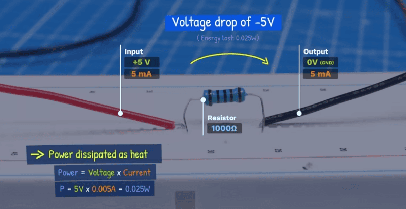
As electrons flow through the material they collide with atoms and this converts electrical energy into heat. As energy is being removed as heat, we also see a voltage drop across the resistor.
A transistor functions something like a switch, allowing a circuit to be turned fully OFF, fully ON, or partially ON by controlling the transistors base current, here I’m using a potentiometer to do that.
The transistor has three terminals: the collector, e mitter and base. This one controls the transistor.
The main current path runs from the collector to the emitter, but by default, the transistor blocks this path.
When a small current is supplied to the base, it enables a much larger current to flow from the collector to the emitter.
The more base current supplied, the more collector current the transistor allows through the main path, up to its maximum rated limit — which should not be exceeded to avoid damaging the device.
If the base current decreases, the collector current also decreases proportionally.
If the base current stops, the transistor immediately blocks the current in the main path, effectively switching the circuit OFF.
The base current can only flow when a positive voltage is applied to the base (relative to the emitter). If the voltage polarity reverses, the base current won’t flow, so the main path is blocked. We will see why that’s important in just a moment.
So, we have a small current flowing through path B, which turns the transistor partially on, and allows a larger current to then flow through path A.
Notice the toroid consists of two separate wires coiled around a ring made from a ferrite material. That just means electricity can’t flow through it, but a magnetic fields can.
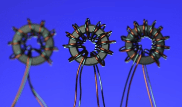
I find that Between 8 and 12 turns of enamelled copper wire will work well for this circuit.
Whenever current flows through a wire, it will generate an electromagnetic field around the wire. If the current changes direction, the magnetic field reverses direction. We can also see this by placing some compasses around a wire.
Using the right-hand grip rule, If you point your right hand thumb in the direction of conventional current through the wire, your fingers will curl around in the direction of the magnetic field lines.
When we wrap the wire into a coil, something interesting happens. The magnetic field of each loop will combine to form one large magnetic field. We call this an inductor.
This magnetic field will have a north and south polarity.
We could wrap the wire in either the clockwise or counterclockwise direction.
When current is applied from the left side, the magnetic polarity depends on the direction the coil is turned.
If current is applied from the right side, this polarity is reversed.
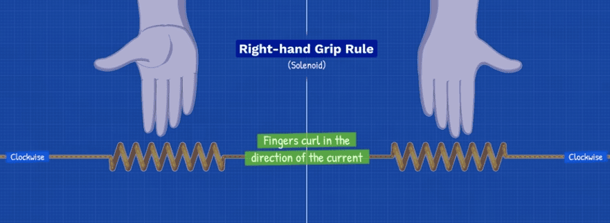
We can determine the polarity using the right hand rule for Solenoids. Our fingers curl in the direction of conventional current flow through the coil and the thumb points to the north pole.
Try it yourself. Tell me in the comments section where the north pole is in this example. I’ll give you the answer at the end of the video.
When current increases, the magnetic field grows because it’s storing more energy. When the current is constant, the magnetic field is also constant. When the current decreases, the magnetic field will also decrease and release this stored energy.
But, inductors don’t allow current to change instantly.
When current increases, the inductor generates a voltage in the opposite direction of the applied voltage. This makes it harder for the current to rise quickly. We call this self inductance.
When current is constant, the inductor stops opposing and behaves like a regular wire. It still has a magnetic field, but it will not generate an opposing voltage.
When current decreases, the inductor generates a voltage which will try to keep the current flowing in the same direction for as long as possible.
So the opposing voltage only occurs when there is a change in current and the magnetic field varies with the current.
Notice the magnetic field is spread out around the coil, which isn’t very efficient. That’s where the ferrite core comes in. We can place the coil around a ferrite core, this channels and conc entrates the magnetic field lines, keeping them tightly contained.
Now, If we add a second coil to the toroid core, the magnetic field generated by the first coil will flow through the second coil.
What do you think will happen to the second coil?
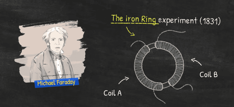
Well, this was an experiment performed by Michael Faraday in 1831 and he noticed that… nothing happens. But, then he realised that when the circuit was turned on or off, it did induce a voltage and therefore current, in the second coil.
This happens because the current was changing which created a changing magnetic field, either increasing as it switched on, or decreasing as it switched off.
So Faraday discovered that a current can produce a magnetic field, and a changing magnetic field can produce a current in a nearby coil. We call this effect mutual inductance.
If we connect a coil to a device called a galvanometer, the dial moves when current flows in the loop. A changing magnetic field will cause this.
As the magnetic field moves towards the coil, the coil experiences an increasing intensity of the magnetic field, this disturbs the coils electrons causing a current to flow. But, when the magnet stops, the current stops, even though the magnetic field is still present. It’s constant, so it doesn’t cause a disturbance. When we move the magnet away, the coil will again experience a change, the magnetic field is decreasing in intensity.
The faster we move the magnet, the stronger the induced voltage, because the coil is experiencing the change in magnetic field much faster. So the rate of change has increased.
We can notice that the dial deflects into the positive or negative as the magnet moves. Meaning current is changing direction in the loop.
If we take a loop of wire, when we move the north pole of a magnet towards it, the magnetic field lines disturb the wire and cause a current to flow in this direction, why? Because that creates a magnetic field in this direction, which will oppose the approaching magnetic field.
When the magnet stops, the current stops and so does the magnetic field. When the magnet is removed, the current flows in the opposite direction which generates an opposing magnetic field to oppose the change.
If the south pole is applied, the current and magnetic field are reversed to oppose this.
This is known as Lenz’s law. It’s named after Heinrich Lenz’s experiments in 1834.
So when our primary coil increases in current, the secondary coil experiences an increasing magnetic field, it will create it’s own opposing magnetic field to resist the change, so current flows in this direction. From that we know the polarity, current would flow out of the positive like a battery.
When the primary current becomes constant, the core holds a constant magnetic field, so no voltage and current is induced into the secondary coil.
But, when the primary current reduces, the core’s magnetic field reduces, so the secondary coil tries to prevent this with a magnetic field, and the current and polarity reverse.
We can see that using this coil, connected across two LED’s in opposite polarities. One flashes as the magnetic field enters, then the other flashes when it exits. Led’s only work one way, so this indicates the direction of current flow and the polarity of the circuit.
So in our toroid, we have two coils, side by side. If we apply a small current in path B, this would therefore have a weak magnetic field around it.
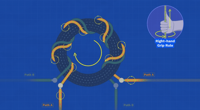
If we apply a larger current through path A, this would have a stronger, more dominating, magnetic field around it. Meaning that coil A will induce energy to coil B.
And since any induced current is going to flow opposite to the change, the only way these coils will work well together is if we apply current to these paths in the opposite direction.
Let me show you that. The largest current is passing through this wire.
That will create a magnetic field in this direction, which causes a magnetic field around the core like this.
That magnetic field is passing through the second coil, so that coil will try to oppose this by generating a magnetic field in the opposite direction, which causes the current to flow in the opposite direction, this can be added to the current from an external source, for example, a battery.
All this happens instantaneously, as the current increases up from zero up to its maximum value. At that point the magnetic field will no longer change, so no voltage and current will be induced into the other coil.
So we have one coil, with a larger current, transferring energy into the core which will then transfer that energy to the other coil. The First Law of Thermodynamics tells us that Energy cannot be created or destroyed, only transformed. So we use that here to boost the output.
But, what would happen if the currents were flowing in the same direction? Well, we have already have established that the (dominant) current in one coil will induce a current in the opposite direction of the other coil.
If we try to apply current in the same direction as the dominant one, this will fight against the induced current that was generated.
But now, if we apply current in the opposite direction, this will be added to the induced current giving us that extra boost.
Ok lets put this all together. The moment the switch is closed, a small current will flow through path B, which partially turns the transistor on.
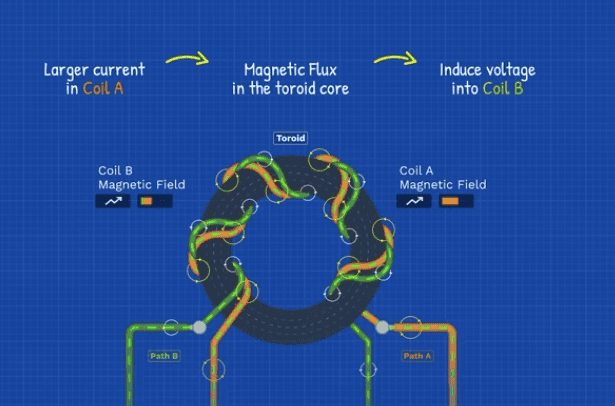
This allows a larger current to begin flowing through path A. This begins to generate a magnetic field in the toroid core and as this builds up it will induce a voltage into coil B.
Since the battery is already providing a small current through coil B, the induced voltage will add to this and boost the base current.
This increase allows the transistor to turn on a little bit more, and that allows more current to flow through coil A, which causes a stronger magnetic field which induces even more voltage and current into the base pin. This keeps repeating, but it can’t continue forever.
The toroid core can only store a limited amount of magnetic energy. As the current continues to increase through coil A, more and more energy is stored in the magnetic field around the core, but eventually the core becomes saturated, it can’t hold any additional energy. At this point the magnetic field stops changing and momentarily becomes constant.
Remember, only a changing magnetic field can induce a voltage in a coil. So, the moment this happens, coil B stops receiving an induced voltage. Without this extra boost, the base current drops suddenly.
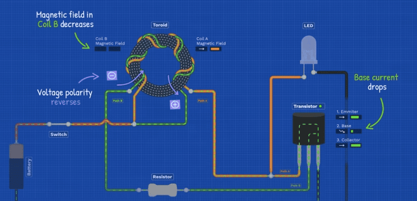
At the same time, the decreasing magnetic field causes coil B’s polarity to reverse, sending a negative voltage to the base pin. This will cause the transistor to instantly turn off and cuts off path A.
The current flowing in Path A is suddenly interrupted, and inductors try to prevent sudden changes in current.
The coil has all this energy stored in the magnetic field, as this suddenly collapses, the polarity reverses and it generates a large voltage spike, to try and keep the current flowing and force the current through whatever path it can find.
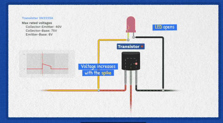
We can actually see this spike by connecting an oscilloscope to the circuit. These spikes are huge compared to the voltage of the battery. These can potentially damage the transistor, so be careful.
This voltage spike could slam into the transistor, which could damage it. But, remember we have an LED across here.
So the voltage increases with the spike until it reaches the LED’s threshold voltage, where the LED will open to allow current to pass through like an escape route, and as this happens it generates a burst of light.
You can also see this moment clearly on the oscilloscope as the voltage spike flattens out, that’s when the LED conducts.
This entire process repeats over and over, hundreds of thousands of times per second. And because this happens so quickly, the LED appears to stay constantly on, to the human eye even though it’s actually flashing on and off with each pulse.
That’s because the LED acts like a diode and only conducts in one direction. When current passes through it, it emits light.The symbol looks just like a diode, except it has these small arrows indicating it emits light.
Inside the LED is a semiconductor material made from two different layers. This acts as a barrier stopping the flow of current. But when a sufficient voltage (pressure) is applied, the electrons can make the jump across this barrier. The electrons will release energy during this process by emitting photons, which travel as a wave and we see this as visible light.
The minimum voltage required for the LED to turn on and produce noticeable light is the threshold voltage, the forward voltage is the normal operating voltage.
Engineers mix different materials to produce photons with certain wavelengths, the length of the wave determines the colour we see and a certain voltage is required to achieve that, depending on the materials used.
We have been using a white LED which needs a higher voltage, and that proves how our low voltage source can generate much higher voltages.
But anyway, that’s how the circuit works.
If you want to build this yourself, you can order the kit with all the components.
Or you can order just the boards from our sponsor PCBWAY who offer CNC machining, 3D printing and of course PCB fabrication services. Do check them out HERE.
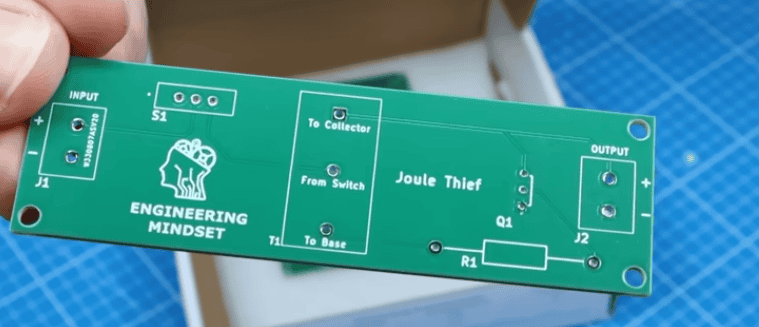
If we scroll down, you’ll see that the order page has been auto-populated with all the project details like the board’s dimensions, the number of layers, and thickness, so we can leave those the same. We can choose the board colour from the options, but I’ll leave it as green. The only thing I will change is the surface finish, selecting the lead free option. And I will also click specify location for the product number. That will just print here on the board, which is later hidden.
So then just choose your country and shipping method, make payment and you will receive a PCBWAY box like this with your boards in. You’ll then need to add your own components.

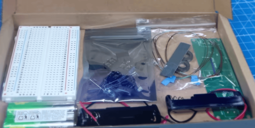
Or, if you choose our kit, everything you need is included. Every component, every material, all in one box.
We’ve even included two of each component. Why? So you can first build a prototype version on the breadboard, following our step-by-step instructions, including guidance on component placement and how to wind the toroid correctly.
Once that’s assembled, you can power it up and run a test to make sure everything works just as it should.
Then, once you’re happy with the results, it’s time to move on to the real deal: soldering the components onto the PCB. This gives you a robust, professional looking version of the project, ready to show off or put to work. You can experiment with the board for other projects. Let me know what you tried and how it came out.
🛠️ Build the kit yourself 🛠️ Want to build the kit at home, click here:👉 https://tinyurl.com/Joule-Thief-Kit
Want to order just the PCB, click here:👉 https://tinyurl.com/Get-PCB-only


")
 Pressure Enthalpy Chart")


")

")


