

LED Circuit Design. Learn how to design LED circuits. How to calculate resistor size, how to protect LED, how long will a battery power a circuit, how to calculate resistor power rating, how to connect LED and much more.
Scroll to the bottom to watch the YouTube tutorial.

These are LED’s, or light emitting diode. If we pass a current through one, it produces light. But, if we exceed it’s voltage and current limit it will instantly be destroyed. The LED has a tiny wire inside, this can only handle a certain amount of current passing through it. When we look at an LED being destroyed under a microscope, we can see the tiny wire exploding inside. So how do we connect the LED’s, how do we reduce the current to keep the LED’s safe and how long will a battery power our circuit for. That’s what we’ll be covering in detail in this article.
LED Protection
To protect our LED’s, we use a resistor. The resistor is going to make it harder for electrons to pass through. The electrons are going to collide and this will generate heat. The resistor will become hot and we can see that with a thermal imaging camera. For example, this one is over 150 degrees Celsius at just 12V with a current of 6milliamps, so we definitely do not want to touch this.
The resistor can be placed on either side of the LED. Although we traditionally install this on the positive side. The reason it can be installed on either side, is because the resistor is restricting how many electrons will flow in this simple series circuit. The resistor acts something like a traffic jam, reducing how many electrons can flow. Most people incorrectly assume it acts like a speed bump and that the electrons must slowing down just before the resistor and then speeding up again. The speed of the electrons remains constant, the number of electrons flowing is what changes.
The higher the resistor value used, the lower the current will be and so the dimmer the led will shine.
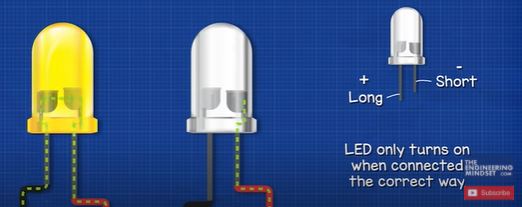
We need to remember that LEDs will only allow current to flow in one direction. With the positive connected to the long lead, and the negative connected to the short lead. If we connect the LED the other way around it will simply block the current and the LED will not turn on. You can test the circuit yourself, take a RED LED, a 9V battery, a resistor of between 360 and 390 Ohm, another higher value resistor of between 3 kilo-Ohms and 9.1 kilo-ohms and a multimeter.
Connect the low value resistor and the LED to the battery in series and the LED will turn iluminate. I’m using a breadboard for this, which makes it very quick and easy to test electrical circuits, but you can also just twist the wires together, you can solder them or use some connectors and it’ll all work fine for this simple experiment.
Notice that if we turn the LED around, we see that it blocks the current so it will not illuminate. It only works in one direction. If we replaced the resistor with the high value 9.1 kilo-ohm resistor we see the LED is very dim. We can also connect them in parallel to compare the brightness. SO now with the 360 ohm resistor and the LED in series, we can connect our multimeter into the circuit, making sure to place the multimeter into the current reading mode. We should see somewhere between 17 and 20 milliamps depending on which LED and resistor you’ve used. We can switch the position of the LED and resistor, it will work fine and give us the same current reading.
Now remove the multimeter from the circuit and place the multimeter into the DC voltage mode.
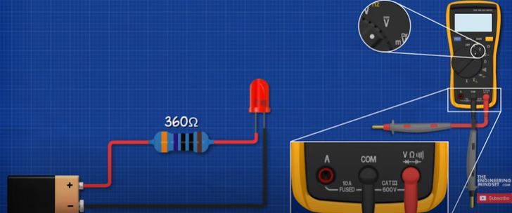
Measure across the two far ends of the circuit and we should see around 9 volts. This is what the battery is providing to our circuit and it is also equal to the total voltage drop of the circuit. Now measure across the LED and we should see around 2 volts. This is the voltage drop of the LED, its removing two volts from our circuit. Now measure across the resistor and we should see a voltage drop for the remaining 7 volts. So 2 volts plus 7 volts is 9 volts which is the same as our battery. You might have noticed that the values measured weren’t exactly 2 volts, 7 volts or even 9 volts. There’s always going to be a difference between the design and actual measurement. For example, this resistor was rated for 390 Ohm but when we measure it, it’s actually 386 Ohms. Each component including your multimeter will have an error tolerance, it will be close to the design value but never exactly this value. For most circuits like these simple ones, it doesn’t matter. We can assume the design values are correct. Just remember that the values we calculate will always be slightly different to our actual measurements.
We also need to know about the forward voltage. This is basically just the voltage drop we measured earlier.
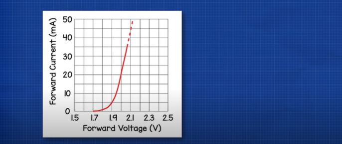
The manufacturer will provide a chart like this one, which shows the forward current at a given forward voltage. So if we connect a voltage source across the leads and apply 2V we should see 20milliamps of current flow. If we applied 1.6V we would see 0 milliamps because the LED will be off. The chart for this LED begins at around 1.7 volts so we know that we need to provide a minimum of 1.7 volts for the LED to start illuminating.
We can test our LED’s minimum opening voltage using a multimeter. If you select the diode mode on your multimeter and then connect the red lead to the long anode and the black lead to the short cathode of a red LED, we should see something like 1.7 Volts, so this is the minimum voltage required to turn the LED on.
Most standard LED’s are rated for a current of 20 milliamps or 0.02 amps. We want to try and stick to this value. If we go below this then the LED will be dim, if we go too far above this then the LED will be destroyed. We can go above 20mA but the lifespan of the LED will reduce the higher we go. We’ll see how to calculate that a little later in the article.
The RED led typically has a voltage drop or forward voltage of 2Volts and this will result in 20milliamps of current in our circuit. We can test that with a DC power supply, when I set the voltage at a constant 2Volts, we see 20 milliamps of current. But, not all LED’s are created equally, this one doesn’t reach 20 milliamps until 2.1 volts are supplied, and this one doesn’t reach 20 milliamps until 3.7 volts is supplied. This variance is due to the materials used and also the manufacturing process taken. So, you should alesud try to use LED’s from the same batch and also from reliable manufacturers.
LED’s come in different colours and each colour has a different voltage drop also, so you’ll need to test this or you can just look this up from a chart of typical values like this one.
LED’s also come in many different colours and each colour has a different voltage drop also. So you will need to look these values up from the manufacturers data or you can also test them yourself, or you can use these typical values from these standard charts but they might not match the LED you actually have.
OK, that’s the basics covered so lets move on and make some example circuits.
Simple LED Circuits
Let’s say we have a 3 volt supply and we want to connect this single RED LED. What resistor do we need? Well, we know that this wire is 3 Volts and this one is our ground wire which will be 0 volts.
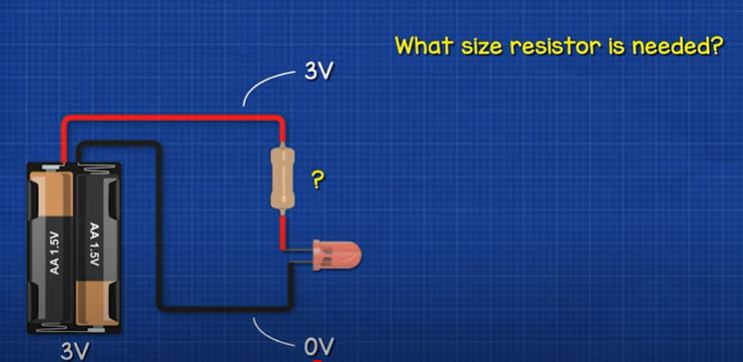
The LED has a voltage drop, of around 2 volts. And so our resistor needs to remove the remaining voltage. So, 3Volts minus 2Volts = 1Volt. We know the LED needs a current of around 20milliamps so 1 volt divided by 0.02amps equals 50 Ohms of resistance. Make sure you convert your milliamps to amps for this calculation. To make it easier we do have a calculator on our website where you can just input your values, check that out HERE.
Ok, now you try to solve this one before I do. Lets say we have a 9 volt battery and we want to connect a yellow LED which has a voltage drop of 2 volts and requires 20 milliamps of current. So What size resistor is required? Well we have a 9 volt supply, so subtract 2 volts for the LED and that leaves us with a 7 volt drop for the resistor. The current is 20milliamps so 7 divided by 0.02Amps equals 350 Ohms of resistance.
Now the problem is that we don’t have a 350 ohm resistor. We only have a 330 Ohm or a 390 Ohm, so which one should we use? As we saw earlier, we need to ensure the current doesn’t exceed 20milliamps so we have to calculate which resistor suits us best.
To do that we just divide the required voltage drop of 7 volts by the resistor value of 330 Ohms to get 0.021Amps and then if we do the same for the 390 Ohm resistor, we will get 0.018 Amps. Both of these values are very close and both will work, but to be safe we choose the 390 Ohm resistor as our LED will therefore last longer. We can also combine resistors to get the exact value we need and I’ll explain that later in the article.
We will also need to choose the resistor power rating. We can calculate this using the formula: Power = current squared X by resistance – so 0.018Amps squared multiplied by 390 Ohm gives us 0.126 Watts so a ¼ watt rated resistor will be fine for this circuit.
How long will the battery power our circuit for? Lets say this battery is rated for a typical 500milliamp hours, we simply divide this by our total circuit current, which in this case is 18milliamps. So 500 milliamp hours divided by 18 milliamps will give us around 27 hours. Although this is the very maximum it would power our circuit for, in reality it probably won’t achieve this.
Ok so what if we wanted multiple LED’s? One option is to connect them in series.
In this design, The voltage drop of each LED will add together. So the total voltage drop in the circuit shouldn’t exceed the battery.
Therefore a 3 volt battery can only sufficiently power 1 LED at 20 milliamps and 9Volt battery can sufficiently power 4 LED’s.
If we connect 4 LED’s, and connect this to our DC bench power supply, we see that they do not turn on until their total combined minimum forward voltage is reached at around 6.3 volts, however the optimal 20 milliamps of current will not be reached until around 8.6 volts. At 9V the current is around 35 milliamps which is obviously too high, so we will need a resistor.
If we connect 5 leds, they won’t turn on until around 8.3 volts. At 9 volts they are all on, but the current is very low, so the LEDs are dim, that’s because the voltage isn’t enough to fully power the LED’s. The optimal 20 milliampd isn’t reached until 10.7 volts in this example.
So we can use this method but we are limited by the voltage of the battery.
What if we want more LED’s? Well, we need to connect them in parallel.
We can either place a resistor on each LED, or we can use one resistor to feed all the LED’s. Lets start with the first example.
Parallel Circuit Individual Resistors
This design lets us use different colour LED’s. Although it’s easier to calculate if they are all the same colour.
Lets say we want to connect 6 LED’s to this 9 volt battery. Each led has a voltage drop of 2 volts and requires 20 milliamps. This entire rail is 9 volts and this entire rail is 0 volts. So, each LED will get 9 volts across it. That’s obviously too much, so we will need to place a resistor against each LED. So we have 9 volts subtract 2 volts for the LED, which leaves us with 7 volts. So we need to drop 7 volts on branch. We calculate the resistor value by 7 volts divided by 0.02 amps which equals 350 Ohms. And then we find the power rating, so 0.02 amps squared multiplied by 350 Ohms gives us 0.14 watts so ¼ watt resistor will be used.
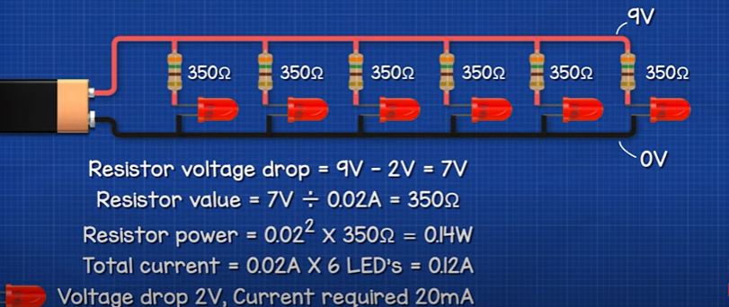
Then we need to add up all the currents in each branch. So 0.02amps multiplied by 6 LED’s, gives us 0.12Amps.
A 9Volt battery has a capacity of around 500 milliamp hours, and our circuit is using 120milliamps so 500 divided by 120 gives us around 4 hours of run time.
We can see there’s still enough voltage on each branch to connect more LED’s. Let’s say we place 3 LED’s on each branch. So each branch has a reduction of 6 volts, therefore 9 volts subtract 6 volts equals a 3Volt drop by the resistor. So 3 volts divided by 0.02Amps gives us 150 Ohm resistor. Notice the total current in each branch didn’t increase, so we can add more LED’s until the maximum voltage is reached.
If we want to use different colour LED’s then we place the different LED’s on different branches and find the suitable resistor. For example we might have a red, blue and green LED.
Each LED has the same current requirement of 20 milliamps but the red led has a voltage drop of 2Volts, the blue has 3.4 volts and the green has 3volts. The resistor for the red LED is therefore 9 volts subtract 2 volts which gives us 7Volts, 7Volts divided by 0.02Amps will lead us to a 350 Ohms resistor. The blue LED is 9 volts subtract 3.4Volts which leaves us with 5.6Volts, so 5.6Volts divided by the current of 0.02Amps leaves us with a 280 Ohm resistor. And the green LED will be 9 volts subtract 3 volts which leaves us with 6 volts, 6 volts divided by the current gives us a 300 Ohm resistor. The total current is therefore 60 milliamps. So the battery will last around 8 hours.
Parallel Circuit Communal Resistors
The other way we can connect the LED’s is by connecting them in parallel and then using a single resistor to limit the total current. For this design, you should only use the same colour or same rating LED’s, we’ll see why that is shortly in this article.
Let’s say we have a 9 volt battery and 3 red LED’s all with a voltage drop of 2Volts and they each require 20milliamps of current. So we just add the currents together, to get 60 milliamps, that current has to flow through this one resistor.
Now as they are connected in parallel they will all have the same voltage difference across them. Therefore we calculate the resistor by 9Volts subtract 2Volts equals 7Volts. Then as all the current is flowing through this one resistor we will need to divide the 7 volts by the 60 milliamps and that will give us a 116 Ohms resistor. The power calculation comes out at 0.49Watts so a half Watt resistor will be used.
The reason we need to use the same rating LED’s is because the voltage difference across here is just 2Volts. So if we use the same rating LED’s they will all illuminate. But if we place a blue LED in the circuit, this requires a higher voltage which it will not be able to get, so this LED will not turn on.
Resistor Tricks
Now, when we deal with these circuits we often find that the resistor value we calculated doesn’t exist or we simply don’t have it in stock. So, we can combine resistors to get the value we need. For example, if we wanted a 200 Ohm resistor, we could place two 100 ohm resistors in series, or we could place 2 x 50 Ohms resistors and a 100 Ohm resistor. The resistor values just add together in series which makes it very easy to increase the resistor value.
To reduce the resistor value, we simple place them in parallel. Then we do some maths to find the equivalent resistance.
Let’s say we have two 10 Ohm resistors, we calculate that using this formula. This is much easier than it looks, just enter this into your calculator and we see it gives us 5 Ohms of equivalent resistance.
Two 5 Ohm resistors will give us 2.5 Ohms of total resistance.
A 200 Ohm and a 50 Ohm resistor would give us 40 Ohms of resistance.
Three 10 Ohm resistors would give us 3.33 Ohms of resistance.
Reading Resistor Values
How can we tell the value of a resistor? Well, these coloured stripes on the body will tell us the value but we need to look it up on a chart. We can get 4 or 5 band resistors typically so lets look at some examples of these.
With the 4 stripe type, the first 2 stripes are the digits which we combine, the third stripe is the multiplier and the 4th stripe is the tolerance.
For example this 4 band resistor is brown, black, brown, gold. Band 1 in equal to 1, band 2 is equal to 0, giving us 10. Band 3 is the multiplier which is 10, so 10 multiplied by 10 is 100 Ohms. Then gold is a tolerance of 5%. So It could be as low as 95 ohms or as high as 105 Ohms. When we measure this one with a multimeter we can see 98.2 Ohm which is within the tolerance. SO we saw that te previous resistor wasn’t very precise.
If we want more precision then we need a smaller tolerance like this 1% tolerance, 5 band type. With this type the first 3 stripes are digits, the 4th is the multiplier and the 5th is the tolerance.
This one is orange, orange, black, black, brown. So this is 3, this is a 3, this is a 0 with a multiplier of one, giving us 330 Ohm’s and the tolerance is 1%. So it could be between 327 ohms and 333 Ohms. When I measure this one with a multimeter we can see it was reading 329.9 Ohms, so it’s perfect.


")


")

")

Hi Paul,
This is a really helpful introduction to LED’s, something I’m just trying to get to grips with for my model railway. You say “Most standard LED’s are rated for a current of 20 milliamps ……. If we go below this then the LED will be dim…”. Other than by trial and error, is there a way to calculate what resistor will dim an LED by say 25% or 50%? Perhaps, 75% / 50% of the 20mA current? Similarly, like the forward voltage, is there a minimum current required for an LED?
Many thanks and kind regards,
Vernon
Excellent article and related youtube video, it has clear logic and animations, it makes teen age student understand it quickly without other of basic knowledges.
Worth to summarize and publish as e-book
Hi, I need to design a circuit for automotive use (so 12V) which uses x60 identical LEDS. The LEDs specs are white 3.3V forward voltage and current is 50mA. I don’t have much room so don’t particularly want to have a separate resistor for every LED and I want the finished item to be as reliable as possible. I had the circuit working with batches of x4 LEDs connected in series (so roughly 12V) and then 15 batches of x4 connected in parallel, keeping the same nominal 12V. I’m an electrical amateur and couldn’t work out how to calculate resistor placement and sizes on my circuit so I tried running it without any. You won’t be surprised to hear they all blew!!! I’m thinking I should probably have a resistor for each batch of x4 LED (maybe batches of x3 would be better) but can anyone help me with the resistor spec calculation? Do I also need to choose a resistor power rating in Watts when I order them? Not sure how to do this on a series / parallel circuit. Any help much appreciated.