

Three phase electricity. In this tutorial we’re going to be learning more about three phase electricity. We’ll cover how 3 phases are generated, what a Cycle and Hertz mean, plot the voltage wave form as it’s being generated, calculate our single phase and three phase voltages.
Scroll to the bottom to watch the YouTube tutorial video on three phase voltage + calculations
So in our last three phase tutorial we looked at the basics of whats happening inside three phase electricity systems and in this tutorial we’re going step it up just a notch and look a little deeper into how these systems work and the basic maths behind them.
We use the plugs in our homes to power our electrical devices. The voltage from these plugs varies depending on where in the world we are. For example: North America uses ~120V, Europe uses ~230V, Australia and India uses ~230V and the UK uses ~230V.
These are the standard voltages set by each countries government regulations. You can look them up online or we can just measure it at home if you have the right tools.
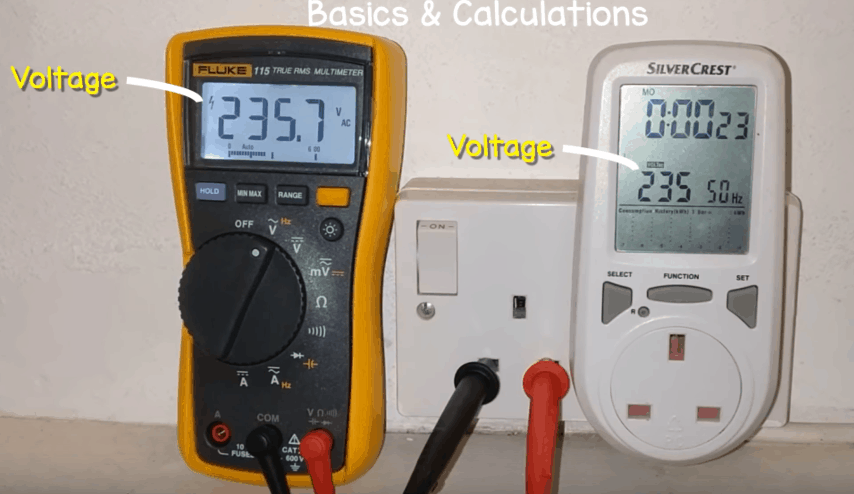
While in the UK, I took some voltage measurements from a standard home plug socket. You can see I get around 235V at this plug using a simple energy meter. Alternatively I can use a multimeter to also read this. The value does change slightly throughout the day, sometimes higher and sometimes lower but it’s kept within a certain tolerance.


If you don’t have an energy meter or a multimeter, these are very cheap and very useful so I recommend you get one.

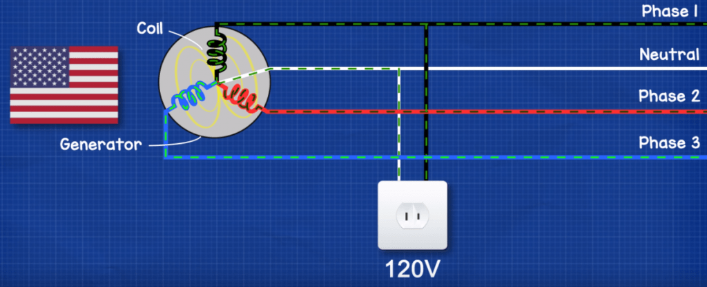
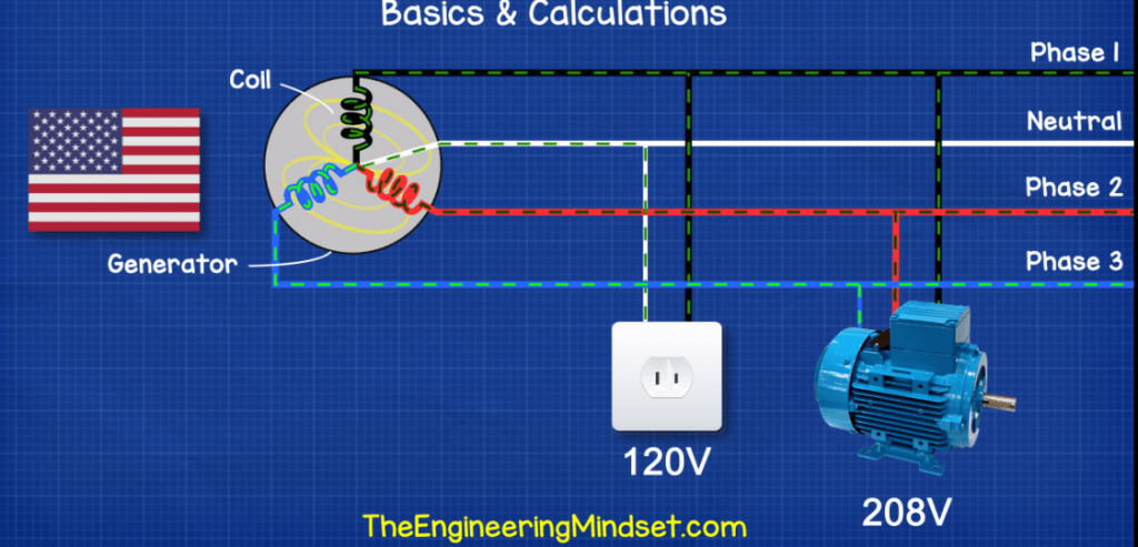
Now these voltages at the sockets in our homes are single phase from a wye connection. They come from connecting between a single phase and the neutral line or in other words just one coil from the generator.
But we can also connect to two or three phases at once, so two or three coils of the generator, and if we do so we get a higher voltage.
In the US we get 120V from a single phase or 208V from two or three phases.
Europe we get 230V single phase or 400V
Australia and India we get 230V single phase or 400V
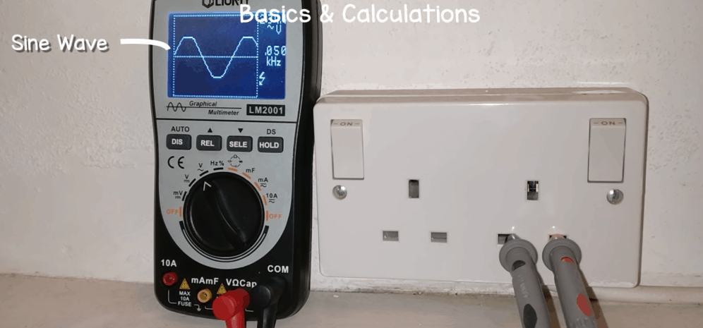
If I connect an oscioscope to the single phase I get a sine wave. When I connect to all three phases I get three sine waves all in a row.

So what’s happening here, why do we get different voltages and why do we get these sine waves?
So just to recap. We get useful electricity when lots of electrons move along a cable in the same direction. We use copper wires because each of the billions of atoms inside the copper material have a loosely bound electron in the outer most shell. This loosely bound electron is free to move between other copper atoms and they do actually move all the time but in random directions which is of no use to us.
To make them move in the same direction we move a magnet along the copper wire. The magnetic field causes the free electrons to move in the same direction. If we wrap the copper wire into a coil then we can fit more copper atoms into the magnetic field and we can move more electrons. If the magnet moves forward in only one direction then the electrons flow in just one direction and we get DC or direct current, this is much like water flowing in a river directly from one end to another. If we move the magnet forwards and then backwards then we get AC or alternating current where the electrons move forwards and then backwards. This is much like the tide of the sea, the water flows backwards and forwards constantly again and again.
Instead of someone moving a magnet back and forth all day, engineers instead just rotate it and then place a coil of copper wire around the outside. We split the coil into two, but keep them connected and then place one on the top and one of the bottom to cover the magnetic field.
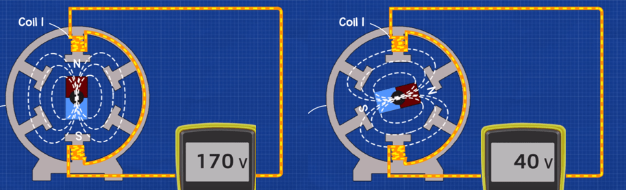
When the generator starts, the north and south pole of the magnet are directly between the coils so the coil doesn’t experience any effect and no electrons move. As we rotate the magnet, the north side passes the top coil and this pushes the electrons forwards. As the magnetic field reaches its maximum more and more electrons begin to flow, but then it passes it’s maximum and heads again to zero. Then the south magnetic pole comes across and pulls the electrons backwards, again the amount of electrons moving varies as the strength of the magnetic field changes during the rotation.
If we plot the change in voltage during the rotation, then we get a sin wave where the voltage starts at zero, increases up to it’s maximum, then decreases down to zero. The south pole then comes in and pulls the electrons backwards so we get negative values, again increasing to a maximum value and then back down to zero.

This one circuit gives us a single phase supply. If we add a second coil 120 degrees rotation from the first then we get a second phase. This coil experiences the change in magnetic field at different times compared to the first phase, so it’s wave form will be the same but It will be delayed. The 2nd phase wave form doesn’t start until the magnet rotates to 120 degrees rotation. If we then add a third coil 240 degrees rotation from the first then we get a third phase. Again this coil will experience the change in magnetic field at a different time to the other two, so its wave will be equal to the others except it will be further delayed and will start at 240 degrees rotation. When the magnet rotates multiple times it eventually just forms an unbroken 3 phase supply with these 3 wave forms.
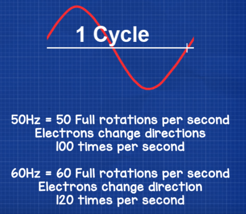
When the magnet completes 1 full rotation, we call this a cycle. We measure cycles in the unit of Hertz or Hz. If you look on your electrical devices you’ll see either 50Hz or 60Hz that’s the manufacturer telling you what type of supply the equipment needs to be connected to. Some devices are able to be connected to either.
Each country uses either 50Hz or 60Hz. North America some of south America and a couple of other countries use 60Hz the rest of the world uses 50Hz. 50Hz means the magnet completes 50 rotations per second, 60Hz means the magnet completes 60 rotations per second.
If the magnet makes a full rotation 50 times per second which is 50 Hertz, then the coil in the generator experiences a change in polarity of the magnetic field 100 times per second (north then south or positive then negative) so the voltage changes between a positive value and a negative value 100 times a second. If it’s 60Hz then the voltage will change 120 times per second. As voltage pushes the electrons to create electrical current then the electrons change direction either 100 or 120 times per second.
We can calculate how long it takes for a single rotation to complete using the formula Time T = 1 / f.
f = frequency. A 50Hz frequency supply therefore takes 0.02 seconds or 20 miliseconds to complete and a 60Hz supply takes 0.0167 seconds or 16.7 milliseconds.
Now we saw earlier that the voltages from your plug sockets are different all around the world.
These voltages are known as the RMS value or the Root Mean Squared value. We’re going to calculate that a little later in the video. The voltage coming out of the plug socks is not constantly 120, 220, 230 or 240V. We’ve seen from the sine wave that it’s constantly changing between positive and negative peaks.
The peaks are actually much higher, for example.
In the US the voltage at the socket reaches 170V
Europe reaches 325V
India and Australia reach 325V
We can calculate this peak or maximum voltage using the formula:

Because the three phases are experiencing the magnetic field at different times, if we added their instantaneous voltages together then we just get zero because they cancel each other out, we’re going to look at that later.
Luckily some intelligent person came up with the idea of using the RMS voltage which is equal to the average power dissipation by a purely restive load, which is supplied instead by a DC direction current.
In other words, they calculated the voltage needed to power a restrictive load, such as a heater, powered by a DC supply. Then they worked out what the AC voltage needed to be to produce the same amount of heat.
Lets rotate the magnet in the generator very slowly and then calculate the voltages for each segment and see how this forms the sine wave for each phase.
SAVE TIME: Download our Three Phase Excel Sheet here
USA 👉 http://engmind.info/3-Phase-Excel-Sheet
EU 👉 http://engmind.info/3-Phase-Excel-EU
INDIA 👉 http://engmind.info/3-Phase-Excel-IN
UK 👉 http://engmind.info/3-Phase-Excel-UK
AUSTRALIA 👉 http://engmind.info/3-Phase-Excel-AU
If we divide the circumference of the generator into segments, 30 degrees apart to give us 12 segments, we can see how each wave is made. I’ll also draw a graph with each of the segments so we can calculate the voltage and plot this. By the way, you can divide this into as many segments as you like, the smaller the segment the more accurate the calculation.
First we need to convert each segment from degrees into radians. We do that by using the formula:

For phase one, we calculate the instantaneous voltage at each segment using the formula.
(Instantaneous voltage just means the voltage at a given instance in time)

So for example at 30 degrees roation or 0.524 radians we should get the value of
84.85 for a 120V supply
155.56 for a 220V supply
162.63 for a 230V supply
169.71 for a 240V supply
Just complete that calculation for each segment until the table is complete for 1 full cycle.
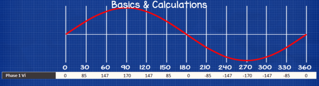
Now if we plot this, then we get a sine wave showing the voltage at each point during the rotation. You see the values increase as the magnetic field becomes stronger and forces more electrons to flow, then it decreases until it reaches zero where the magnetic field is exactly between north and south across the coil so it has no effect. Then the south pole comes in and starts to pull the electrons backwards so we get a negative value and it increases as the south poles magnetic field changes in intensity.
For phase 2 we need to use the formula

“(120*pi/180))” this end part just takes into account the delay because the coil is 120 degrees from the first.
Example at 30 degrees for phase 2 we should get the value of
-169.71 for a 120V supply
-311.13 for a 220V supply
-325.27 for a 230V supply
339.41 for a 240V supply
So just complete that calculation for each segment until the table is complete for 1 full cycle.
For phase 3 we need to use the formula

Example: at 30 degrees for phase 3 we should get the value of
84.85 for a 120V supply
155.56 for a 220V supply
162.63 for a 230V supply
169.71 for a 240V supply
So just complete that calculation for each segment until the table is complete for 1 full cycle.
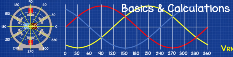
We can now plot this to see the wave form of phases 1.2 and 3 and how the voltages are changing. This is our three phase supply showing the voltage on each phase at every 30 degrees rotation of the generator.
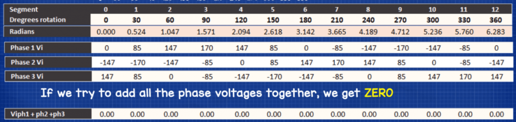
If we then try to sum the instantaneous voltage for all the phases at each segment, we see that they cancel each other out. So instead we’re going to use the DC equivalent RMS voltage.
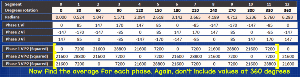
To do that for phase 1, we square the instantaneous voltage value for each segment. Do this for all the segments for a complete cycle.
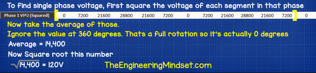
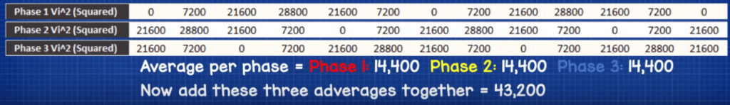
Then add all these values together and then divide that number by how many segments we have, in this case we have 12 segments. Then we take the square root of that number. This gives us our rms voltage of either 120, 220, 230V or 240 volts depending on which power supply you’re calculating for.
This is the phase voltage. That means if we connect a device between any phase and the neutral line, then we get Vrms of 120, 220, 230 or 240V just like you would at the plug in your home.
We now do the same for the other two phases. Square the value of each instantaneous voltage.

If we need more power then we connect between two or three phases. We calculate the supplied voltage by squaring each of the instantaneous voltages per phase, then add all three values together per segment and then take the square root of that number.
You’ll see the three-phase voltage comes out to
208V for a 120V supply
380V for a 220V supply
398V for a 230V supply
415v for a 240V supply
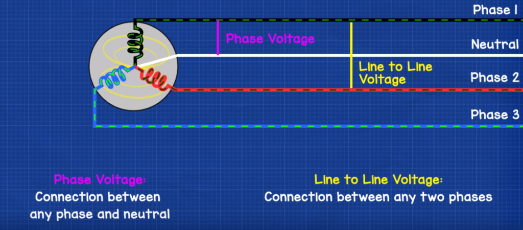
We can get two voltages from a three phase supply.
We call the smaller voltage our phase voltage, and we get that by connecting between any phase and the neutral line. That’s how we get our voltages from our power outlets in our homes because they are only connected to one phase and the neutral.
We call the larger voltage our line to line voltage and we get that by connecting between any two phases. That’s how we get more power from the supply.
In the US for example many appliances need 208V because 120V simply isn’t powerful enough so we have to connect to two phases. In North America we can also get 120/240V systems which works differently. We cover that in another tutorial.


")

")
Thanks for explaining three phase voltage in an easily understandable way. This concept is really difficult to grasp and I could never understand it completely, especially the calculations. I always mess them up. But I think I’ve understood it now.
I now, finally understand 2,3 or more phase systems. My question is, can you connect All phases together for more power, and would it give you more power or heated generator coils ? I only now started to understand 2 and 3 ( or more) , phases of electricity thanks to your videos. Thanks for making it easy for us old fogies to understand. I have an electronic technology degree, but we never covered that in 1973 !
Very good site for engineering persons
Excellent tutorial and YT video, thank you. FYI: √3 ≈ 208÷120 ≈ 380÷220 ≈ 400÷230 ≈ 415÷240.
[…] LEARN MORE HERE: https://theengineeringmindset.com/three-phase-voltage-calculations/ […]