Power Factor Explained. In this tutorial we look at power factor. We’ll learn what is power factor, what is good and bad power factor, how to compare power factor, the causes of power factor, why and how to fix power factor as well as some example calculations to help you learn electrical engineering.
Scroll to the bottom to watch the FREE YouTube tutorial
So, what is power factor?

Power factor is a unit-less number used in alternating current circuits, it can be used to refer to a single piece of equipment such as an induction motor or for the electricity consumption of an entire building. In either case it represents the ratio between true power and apparent power. The formula being PF = kW / KVA. So, what does this mean?
My favourite analogy to explain this is to use the beer analogy.
We pay for a beer by the glass, but inside the glass there is both beer and foam. The more beer we have, the less foam there is so we get good value for money. If there is a lot of foam then there’s not a lot of beer and we’re not getting good value for money.

The beer represents our true power or our kW, kilowatts. This is the useful stuff we want and need, this is what does the work.
The foam represents our reactive power or our kVAr, kilovolt-amps reactive. This is the useless stuff, there will always be some and we have to pay for it but we can’t use it so we don’t want too much of it. (it does actually have a use and purpose but we’ll see why later on)
The combination of these kW and kVAr is our apparent power or our kVA. kilovolt-amps
.
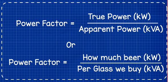
Power factor is therefore the ratio of useful power or true power in kW divided by what we’re charged for in kVA. So it’s telling us how much value for money we’re getting for the power we consume.
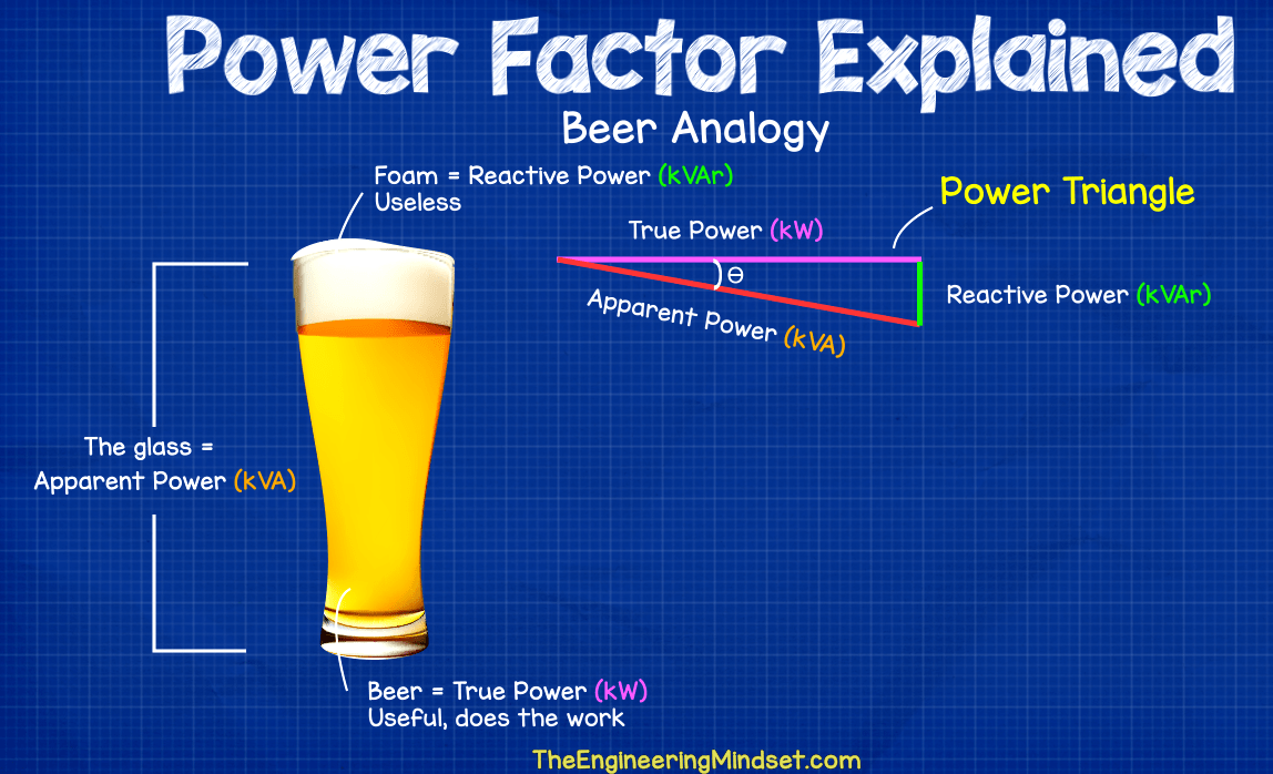
If we very briefly touch on electrical engineering terms we might see this expressed as a power triangle. In this case I’ll draw it as a leading power factor as it’s easier to visualise. The beer or true power is the adjacent line, then we have the foam which is the reactive power on the opposite, then for the hypotenuse side, which is the longest side, we have the apparent power, this is at an angle from the true power, the angle is known as theta.
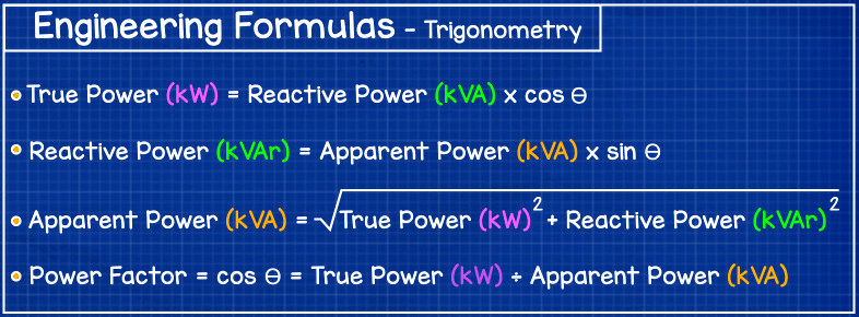
As the reactive power or the foam increases then so does the apparent power or kVA. We could then use trigonometry to calculate this triangle, I won’t in this article as I’m just covering the basics so we’ll just see the formulas you need but we will do some calculations and worked examples later in this article.
If we look at a typical residential electricity bill we’ll typically just see a fee for the amount of kWh’s used because the power factor and electricity consumption will be very low, so the electricity companies tend to not worry about this.
However, on commercial and industrial electricity invoices, especially buildings with smart or interval electricity meters, we’ll likely see charges and information for the amount of kW, kWh’s, kVA’s and kVArh’s used. Large buildings in particular will often see reactive power charges in there also, but this depends on the electricity supplier.
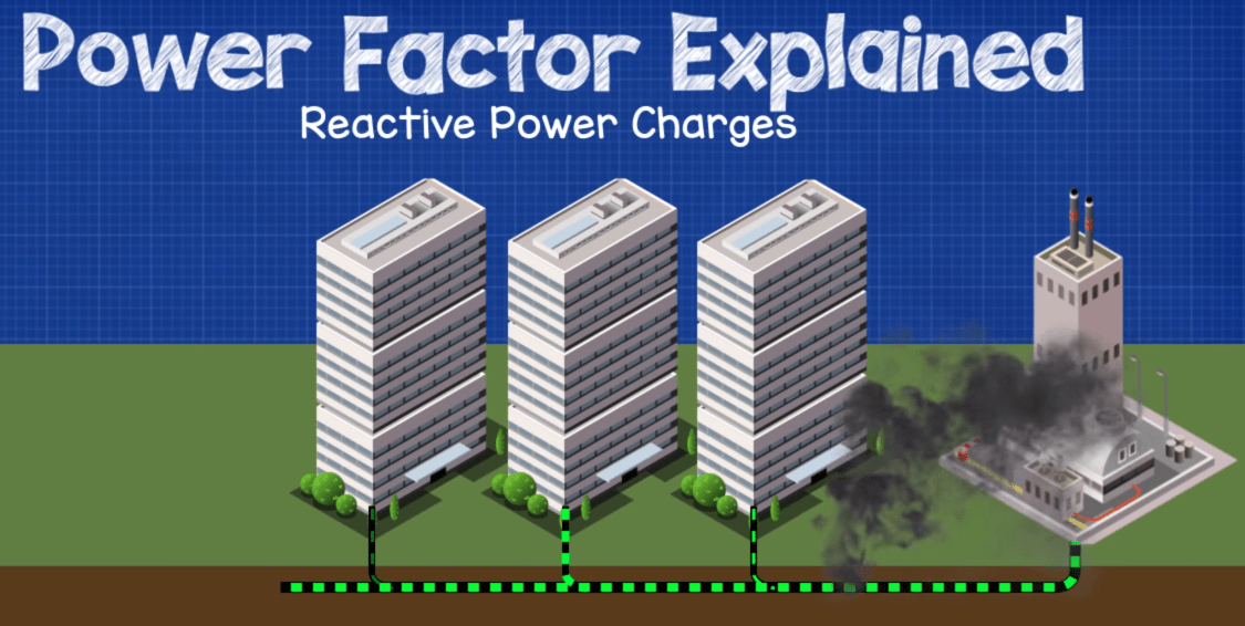
The reason they charge a penalty for this is because when large consumers have bad power factors, they are increasing the current flow through the electricity network and causing voltage drops which reduces the suppliers distribution capacity and has a knock on effect for other customers. Cables are rated to handle a certain amount of current flowing through them. So if a lot of large consumers connect with bad power factors, then the cables could over load, they could struggle to meet demand and capacity agreements and no new customers will be able to connect until they either replace the cables or install additional cables.
Reactive power charges occur when the power factor of a building falls below a certain level, this level is defined by the electricity supplier but it typically starts at around 0.95 and below.
A perfect power factor would be 1.0, however in reality this is almost impossible to achieve. We’ll come back to this later in the video.
In large commercial buildings, the overall power factor is likely to sit in the following categories
Good power factor is generally between 1.0 and 0.95
Poor power factor is anything from 0.95 and 0.85
Bad power factor is anything below 0.85.
Commercial office buildings are usually somewhere between 0.98 and 0.92, industrial buildings could be as low as 0.7. We’ll look at what causes this shortly.

If we compare two induction motors, both have an output of 10kW and are connected to a three phase 415V 50Hz supply. One has a power factor of 0.87 and the other with a power factor of 0.92
Both motors will deliver 10kW of work, but the first motor has a lower power factor compared to the second one, meaning we’re not getting as much value for money.
The first motor will need to draw 11.5 kVA from the electricity grid to provide the 10kW of power.
The second motor will need to draw just 10.9 kVA from the electricity grid to provide the 10kW of power.
This means the first motor has 5.7 kVAr’s and the second motor has just 4.3 kVAr’s.
Remember our kW’s is the beer that’s the useful stuff. The kVAr’s is the foam, that’s the not so useful stuff. The kVA is what we’re going to pay for and that’s the kW + the kVAr.
How did I calculate this?
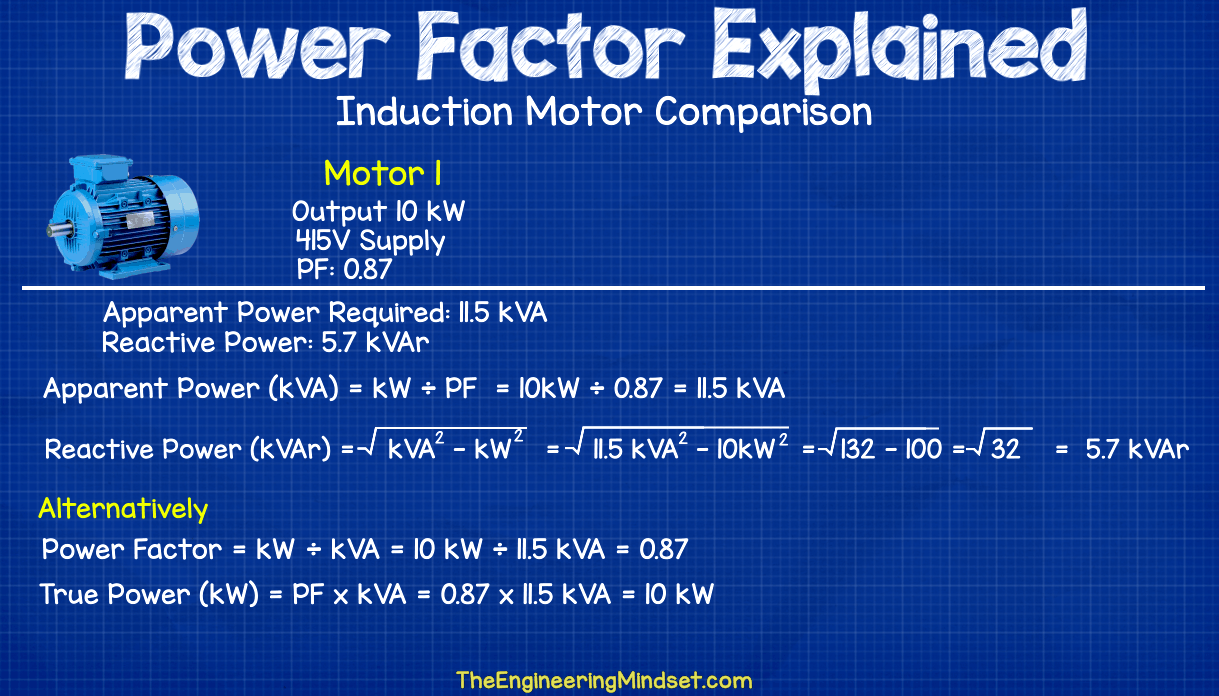
For kVA I used kW divided by Power factor so 10 divided by 0.87 to get 11.5 kVA
kVA = kW / PF
For kVAr I used the square root of kVA squared subtract kW squared, so square root of 11.5kVA^2 minus 10kW^2
kVAr = square root of kVA^2 – kW^2
We could have also found the power factor from the kW and kVA using 10kW divided by 11.5kVA
PF = kW / kVA
We could have found the kW from the power factor and kVA using 0.87 divided by 11.5kVA to get 10
kW = PF x kVA
So what causes poor power factor?
In most cases the power factor is affected by inductive loads.
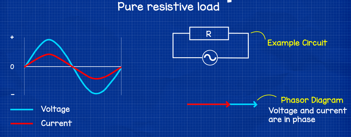
If we had a purely restive load such as an electrical restive heater then the voltage and current wave forms would be in sync or very close. They would both pass their maximum and minimum point and pass through the zero axis at the same time. The power factor in this case is 1 which is perfect.
If we drew a phasor diagram then the voltage and current would be parallel, so all the energy drawn from the electricity supply goes into doing work, in this case creating heat.
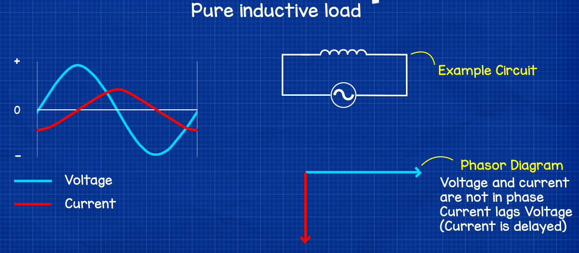
If we took an Inductive load such as an induction motor, the coils magnetic field holds back the current and results in a phase shift where the voltage and current wave forms fall out of sync with the current and so it passes through the zero point after the voltage, this is referred to as lagging power factor.
Earlier in the article I said the foam or kVAr is useless, that’s not exactly true, we actually need some reactive power to create and maintain the magnetic field which rotates the motor. The reactive power is wasted in the sense that we get no work from it but still have to pay for it, although we do need it to be able to do the work in the first place. We covered how induction motors work previously, click here to see that tutorial.
If we drew a phasor diagram for a purely inductive load then the current will be at an angle below the voltage line, meaning not all the electricity consumed is doing work.
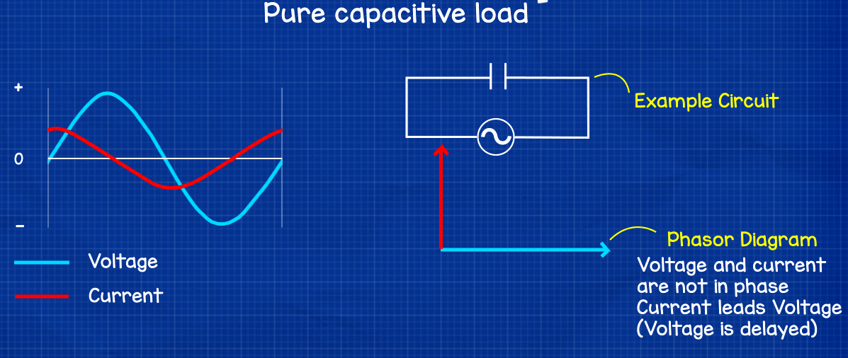
If we took a purely capacitive load then the opposite happens to the inductive load. The voltage and current are out of phase except this time the voltage is held back. This causes leading power factor. Again this will mean not all the electricity is being used to do work, but we have to pay for it regardless.
If we drew a phasor diagram for a purely capacitive load then the current line would be at an angle above the voltage line as it is leading.
Correcting poor power factor
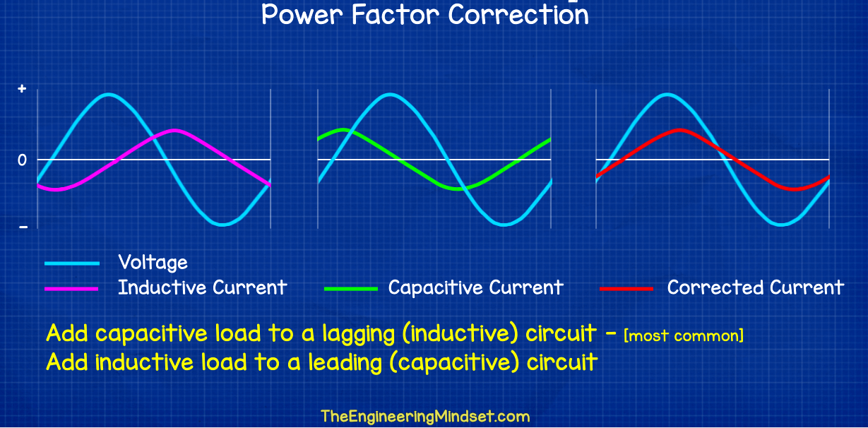
What can we do to correct poor power factor and reactive power charges? In most cases we come across lagging power factor caused by inductive loads, but we can come across leading power factor.
To correct poor power factor, we can add capacitors or inductors to the circuit which will realign the current back into phase and bring the power factor closer to 1. If we have a lagging power factor caused by high inductive loads in the circuit then we add capacitors, this is most common. If we have a leading power factor caused by high capacitive loads then we add an inductive load to the circuit. These need to be calculated and we’ll see some example calculations at the end of the article.
Why fix poor power factor?
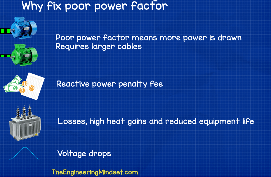
Poor power factor means you need to draw more power from the electricity networks to do the same work, and the cables need to be larger so it’s going to cost more. If the power factor become too low then the electricity supplier might charge you a penalty fee or reactive power charge. Poor power factor can cause losses in equipment like transformers and leads to high heat gains. It can lead to voltage drops and can even reduce the life expectancy of equipment in extreme scenarios.
Capacitor calculations for power factor correction
Lets look at a simplified example of calculating the size of a capacitor to improve the power factor of a load. The building has a 3 phase power supply and has a total load of 50kW of work and has a power factor of 0.78 but we want it to be 0.96 to avoid penalty charges.
Currently the building has a total apparent power (kVA) value of 64.1kVA and we find that by just diving the kW (50kW) by the power factor of 0.78.
It also has a reactive power of 40.1kVAr, we find that by taking the square root of the kVA^2 squared and subtracting it from the kW^2 squared. So take the square root of 64.1kVA squared minus 50kW squared.
Then we calculate what the values should be if we had the power factor of 0.96.
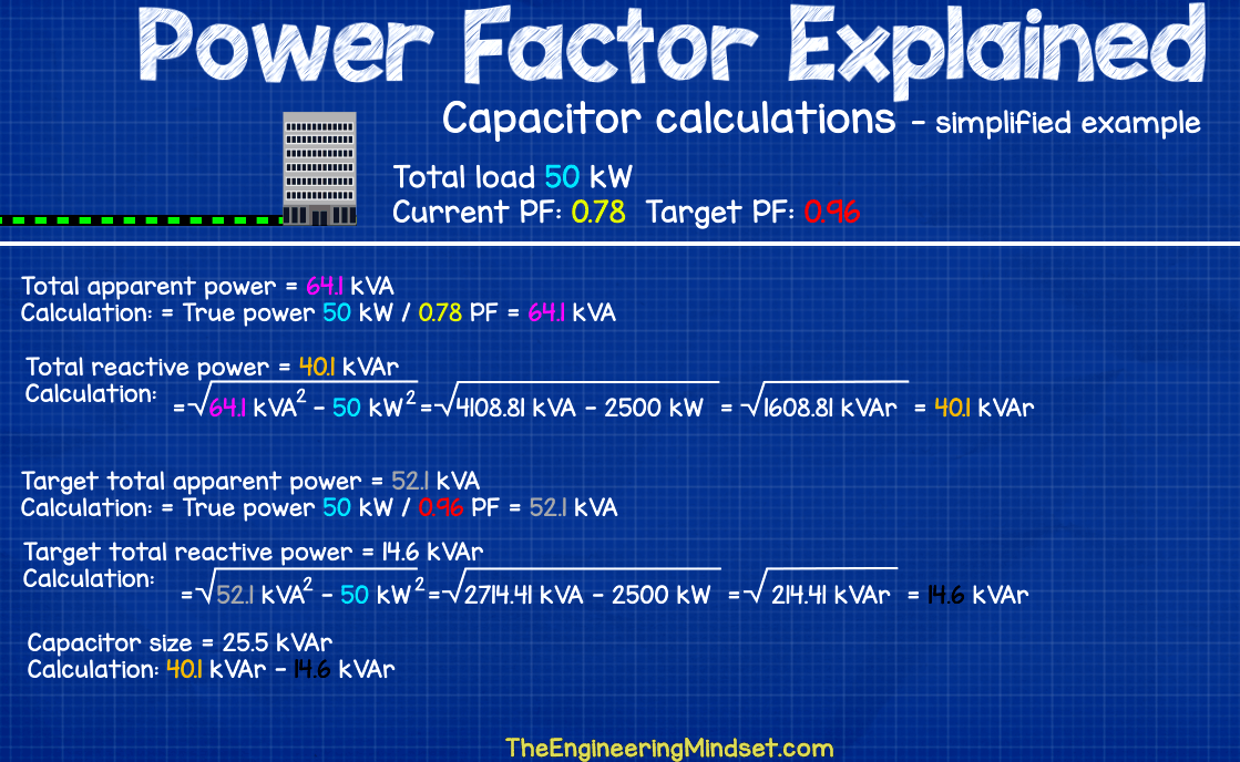
So, our apparent power would be 52.1 kVA, we find that from 50kw divided by 0.96 power factor
Then we find our reactive power which is the square root of kVA^2 squared minus the kW squared so square root of 52.1kVA^2 minus 50kW^2 squared which gives us 14.6kVAr.
The capacitor therefore needs to make up the difference between these two so 40.1kVAr minus 14.6kVAr which equals 25.5kVAr capacitor. This is a simplified example, check with a supplier.







Hey paul, how can we calculate the motor HP rating ?
Thanks. I needed a simple explanation for Board members because of an upcoming change to electrical billing from our utility company. This is great. Your beer analogy is perfect for those of us without engineering mindsets 🙂
It’s very nice to see. I would like to comment your post. You did a great work here. I am happy to share this post to my friends.After all I’ll be subscribing on your feed and I am hoping you write again very soon!
In the table of Engineering formulas (Trigonometry) there is a typo. In the True Power calculation you have reactive power listed as kVA not KVAR
Actually the formula should be True Power=Apparent Power (kVA) x COSƟ
Power Factor expresses the ratio of real power actually used in a circuit to the apparent power delivered to the circuit. The total power demand on the network is usually greater than the real power.
Actually the formula should be True Power=Apparent Power (kVA) x COSƟ
Very well explained
[…] https://theengineeringmindset.com/power-factor-explained/ https://sphera.com/spark/the-sustainability-of-electric-motors/ […]
[…] https://theengineeringmindset.com/power-factor-explained/ […]
is there a part 2 to this video?
I wish I’d heard more about why any given motor (or any other household electrical and electronic device) has a less than perfect PF. Is it flaws in design, materials, or construction, a specific motor or circuit type, etc. Or does a lees-than-perfect PF just “go with the territoy?” What specific factors cause a commercial building have a worse PF than any of the electrical devices used in it? Can a motor realistically have a PF of 1, and if so, can it also perform work? Does it need help starting? Does PF change with load or no-load? Practically speaking, if a motor has a poor PF AND it can be improved with added capacitance or inductance, why didn’t the manufacturer add them? Expense or a trade off with performance? Longevity? Get my drift?
Thanks