

Learn the basic working principle of power inverters, how they work, what they are used for, where we use them and their importance along with worked examples.
Remember electricity is dangerous and can be fatal. You should be qualified and competent to carry out any electrical work.
Scroll down to the bottom to watch the YouTube tutorial
What Is An Inverter?
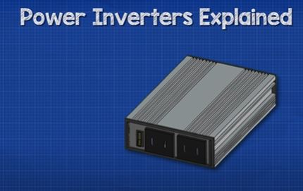
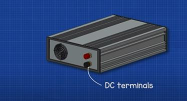
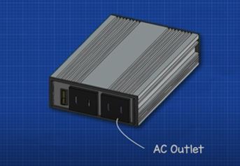
A typical inverter looks something like the above. It has some red and black DC terminals on the back end and on the front end we find some AC electrical outlets.
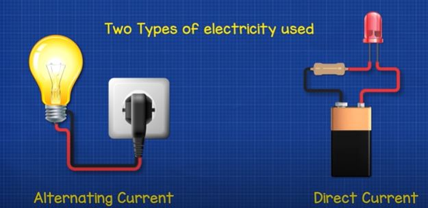
That’s because there are two types of electricity, AC and DC. An inverter is used to convert DC or direct current into AC alternating current.
We can also convert AC into DC with the use of a rectifier, which we’ll cover in a separate article, you can read that HERE.
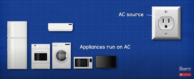
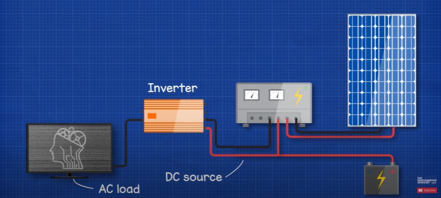
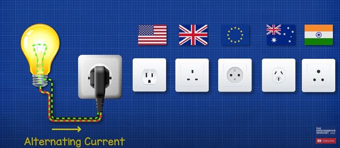
The appliances in our homes are designed to run off an AC supply and they get that from the electrical outlets which all provide AC electricity. However, electricity produced by things such as solar panels and batteries produce DC electricity.
So, if we want to power our electrical devices from, renewable sources, battery banks or even our car, then we need to convert DC electricity into AC electricity and we do that with an inverter.
To understand how an inverter works we first need to understand some fundamentals of electricity.
Electricity Fundamentals
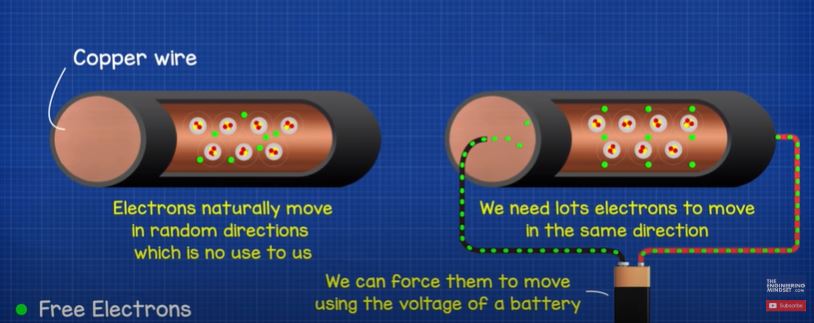
Inside a copper wire we find copper atoms. These have electrons which can move to other atoms, these are known as free electrons because they are free to move around. They will randomly move in all directions but that isn’t any use to us. We need lots of electrons to move in the same direction. We do that by applying a voltage difference across the wire, the voltage is like pressure and will push the electrons.
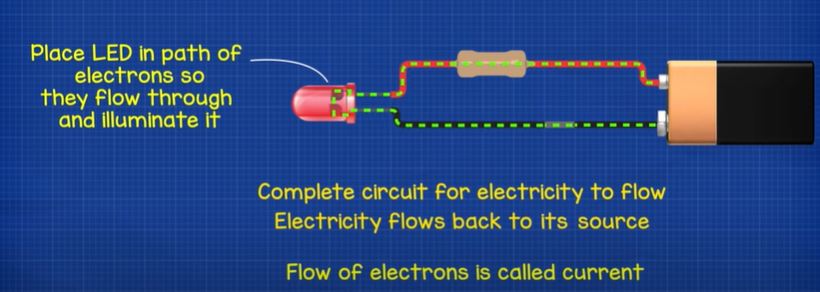
When we connect a wire to the positive and negative terminals of a battery, we complete the circuit and electrons begin to flow. We call this flow of electrons, current. The electrons always try to get back to their source, so if we place things such as lamps in the path of the electrons, they will have to pass through it and this will allow us to do work such as illuminating a lamp.
DC
The electricity from solar panels and batteries is known as DC electricity. This is because in this type, the electricity flows in just a single direction. It flows from one terminal directly to the other terminal. If we reverse the battery, the electrons flow in the opposite direction.
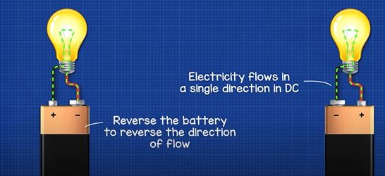
You can think of DC electricity like a river, with the current of water flowing in just a single direction.
These animations use Electron flow which is from negative to positive. But you might be used to seeing conventional current which is from positive to negative. Electron flow is what’s actually occurring, conventional current was the original theory and it’s still widely taught today, just be aware of the two and which one we’re using.
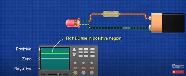
When we use an oscilloscope to look at the electrical wave form for DC, we get this flat line at maximum voltage in the positive region.
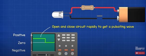
If we cut the power, the line drops to zero. If we turn it on and off repeatedly then we get a square wave pattern between zero and maximum.
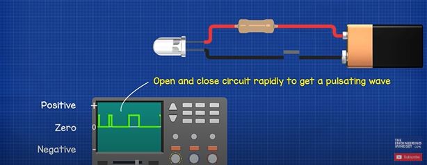
If we pulsed the switch to open and close over different lengths of time then we get a pulsating pattern.
AC
With AC electricity the electrons alternate by flowing forwards and backwards constantly. That’s how it gets its name because the current of electrons alternates in direction. You can think of this type of electricity like the tide of the sea, it constantly flows in and out between the maximums of high tide and low tide.
If we followed the copper wires back to the generator, the wires are connected to some coils of wire which sit within the generator. Inside a basic generator we also find a magnet at the centre which is rotating.
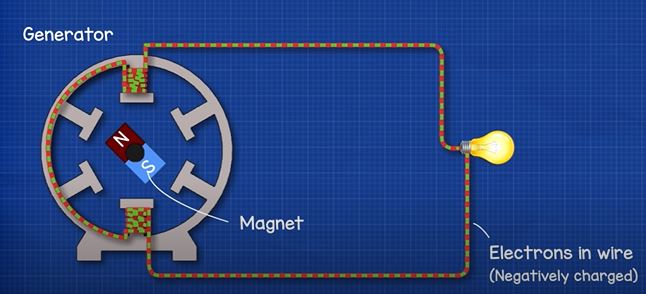
The magnet has a north and south pole or you can think of it as a positive and negative half. The electrons in the wire are negatively charged. As you might already know, magnets push or pull depending on the polarity. As the magnet rotates past the coils, the positive and negative half are going to therefore push and pull the electrons within the copper coils and also through the connected copper wires.
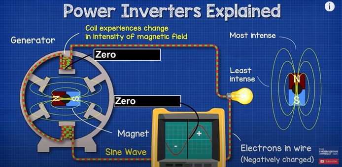
The magnetic field of the magnet varies in intensity. So as the magnet rotates past the coil, the coil will experience a change in intensity of the magnetic field, from zero, up to its maximum intensity and then as it passes the coil, it will decrease again back to zero. Then the negative half comes in and pulls the electrons backwards with the same change in intensity. Each full rotation of the magnet will therefore produce this wave pattern known as a sine wave. The voltage is not constant in this type of electricity and it instead repeatedly moves from zero, up to its peak, back to zero, then to the negative peak and finally back to zero.
Frequency
Frequency refers to how many times this AC sine wave repeats per second.
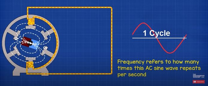
In north America and a few other parts of the world we find 60Hz electricity which means the sine wave repeats 60 times per second, and as each wave has a positive and negative half, this means its polarity will therefore reverse 120 times per second. In the rest of the world we mostly find 50 Hz electricity so the sine wave repeats 50 times per second and therefore the current reverses 100 times per second.
Inverter Circuit
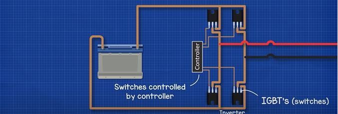
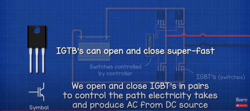
The inverter consists of a number of electronic switches known as IGBT’s, the opening and closing of the switches is controlled by a controller.
These can open and close super-fast in pairs to control the flow of electricity. By controlling the path which the electricity takes and how long it flows in the different paths, we can produce AC electricity from the DC source.
We’re going to animate these using some simple switches to make it easier to visualise.
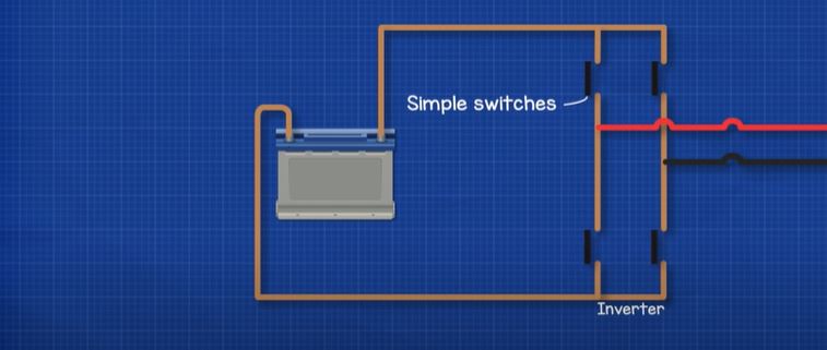
Remember AC is where the current reverses direction. We saw earlier in the video that we can reverse the direction of current by reversing the battery. We could very quickly reverse the battery to produce a rough AC supply. But an easier way would be to connect 4 switches or IGBT’s across our load, such as a lamp. If we open and close these in pairs then we can produce AC electricity. So if we close switches 1 and 4 then the current flows in one direction and if we open those and close switches 2 and 3 we get current flowing in the other direction. So we can use the controller to automatically do this again and again.
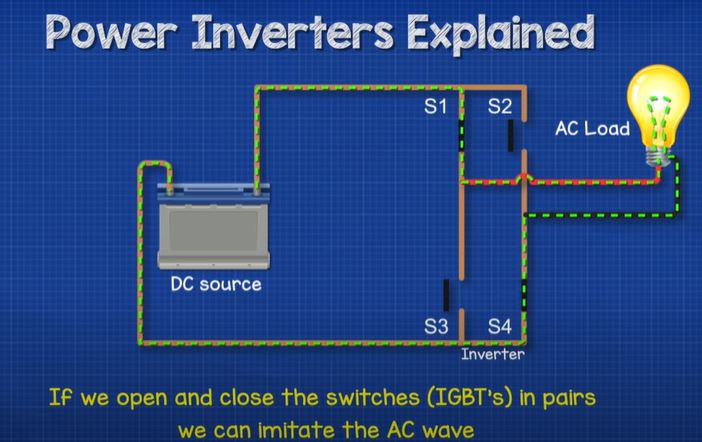
If we did that 120 times per second then we would get 60hz AC and if we did that 100 times per second then we would get 50hz AC.
As we have a low voltage input, we’re going to get a low voltage output. To reach the 120V or 230V required to power our appliances, we will also need a transformer to step up the voltage to a useful level.

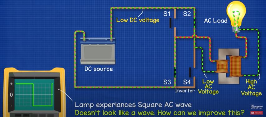
When we look at this through an oscilloscope, we get a square wave in the positive and negative regions. This is theoretically AC because it reverses direction, but it doesn’t look much like an AC sine wave. So how can we improve this?
Pulse Width Modulation
Remember earlier in the article when we said we can open and close the switch at different speeds and duration’s to change the wave form. Well we can do that for this too.
What we do is use the controller to rapidly open and close the switches multiple times per cycle in a pulsating pattern, each pulse varying in width. This is known as pulse width modulation. The cycle is broken up into multiple smaller segments.
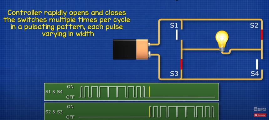
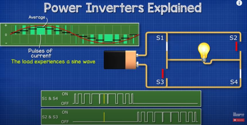
Each segment has a total amount of current that could flow. But by rapidly pulsating the switches we control the amount of flow occurring per segment. This will result in an average current per segment which we see increases and decreases thus giving us a wave. The load will therefore experience a sine wave. The more segments we have the closer it mimics a smooth wave.
We can control the output voltage by controlling how long the switches are closed for. So, we could for example output 240v or 120v by trimming the open and close times.
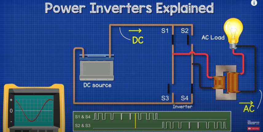
We can control the frequency by controlling the timing of the switches, so we could for example output 60hz, 50hz or 30Hz, whatever is needed for the application.
So that’s how we can take a 12V battery and convert this into a 120V or 230V AC supply by using some IGBT’s, pulse width modulation and a transformer.
What if we wanted more power?
Split Phase, Single Phase and Three Phase Electricity
We also have single phase and three phase AC electricity.
Most homes around the world use single phase electricity. Large commercial buildings as well some homes, especially in Europe, will use three phase electricity.
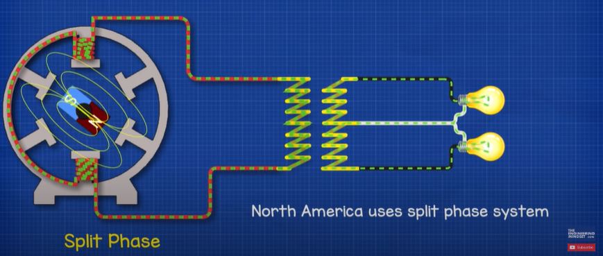
Homes in north America use split phase electricity where a centre tapped transformer splits a single phase in two, which provides two hot wires and a neutral.
We’ve covered how split phase electricity works in detail in a previous article, do check that out HERE.
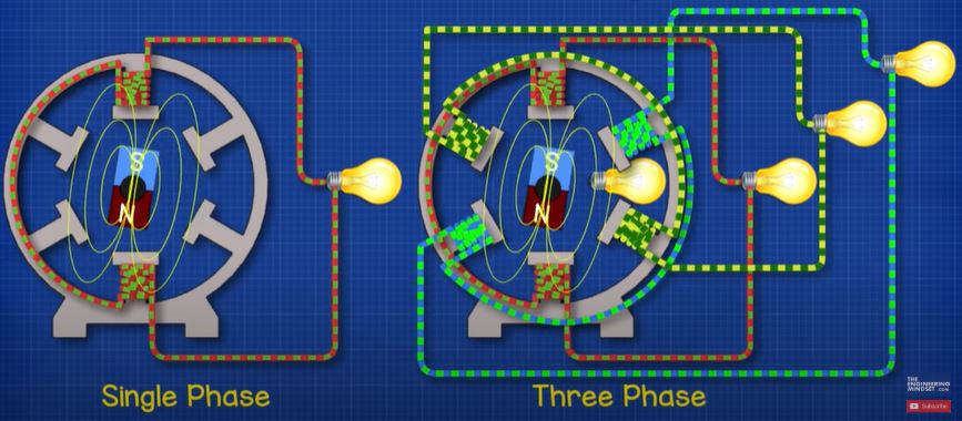
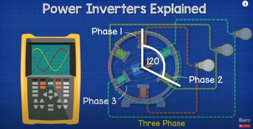
With single phase we have a connection to just a single phase from a generator, so we have just one sine wave. But with three phase electricity we have a connection to each of the three phases. The phases are coils of wire which are inserted into the generator 120 degrees apart from the previous, this means the coils experience the peak of the rotating magnetic field at different times, this gives us our three phases, each with a different sine wave that is slightly out of sync from the previous.
Remember electricity wants to get back to its source in a complete circuit. As the current is flowing forwards and backwards at different times in each of the phases, we can essentially connect the phases together and the current will move between the different phases as the polarity of each phase moves forwards and backwards at different times. Any excess will flow in the neutral back to the source if needed.
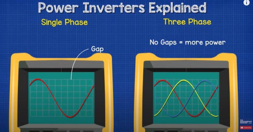
With single phase we have these large gaps between the peaks. But with 3 phase these can be combined to fill the gaps in and therefore deliver more power.
Three Phase Inverters
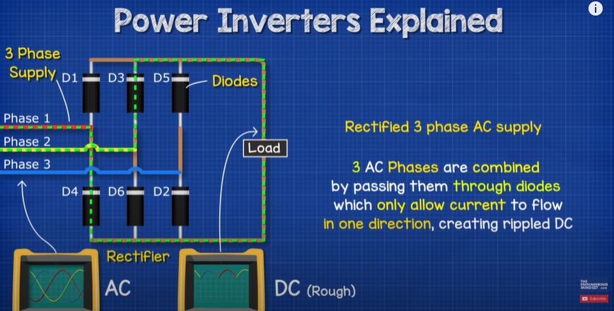
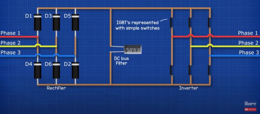
Larger applications require a three-phase inverter, for example to run compressors in large cooling systems, this rectifier will be built into the variable speed drive. The DC supply in this case will be a rectified 3 phase AC supply. That means the 3 AC sine waves are combined together and passed through some diodes which prevent the electrons from flowing backwards, this turns it into a rippled DC. We then use a capacitor to smooth the ripple out into a constant DC supply.
We have covered this in great detail previously, do check that out HERE.
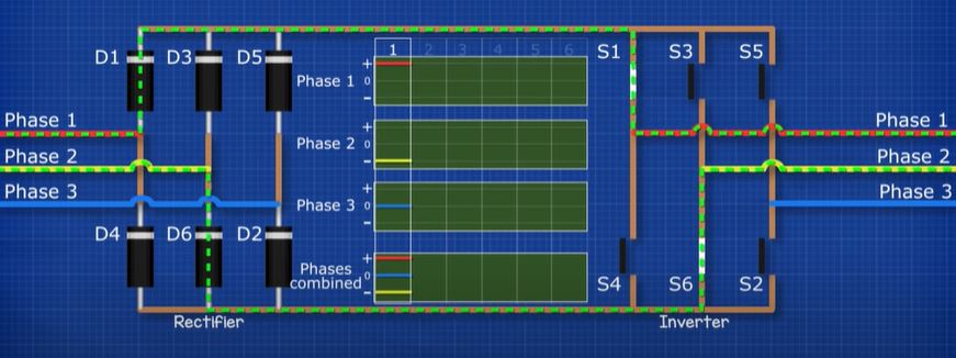
To turn the clean DC into three phase AC, we use a three-phase inverter. For this we use 6 IGBT’s. Again, We’ll animate these as simple switches for simplicity and We’ll number these as follows.
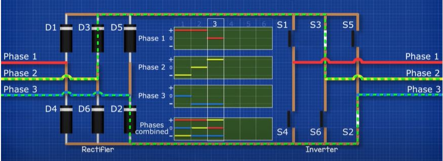
To get our three phases, we need to open and close switches in pairs to direct the flow of current to form our supply and return paths, that way the connected motor will experience Alternating current.
For the three-phase supply, we time the switches to simulate the 3 phases. Let’s see how this works.
First we close switches 1 and 6. This will give us phase 1 to phase two.
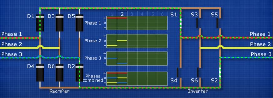
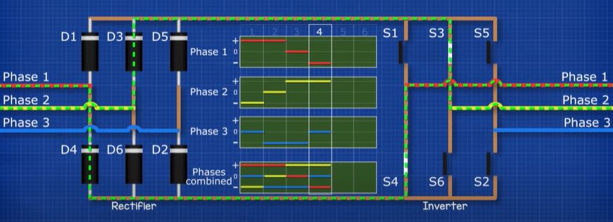
Then we close switches 1 and 2. This will give us phase 1 to phase three.
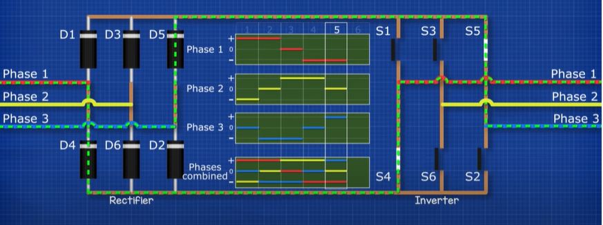
Then we close switches 3 and 2. This will give us phase 2 and 3.
Then we close switches 3 and 4. This will give us phase 2 and 1.
Then we close switches 5 and 4. This will give us phase 3 and 1.
Then we close switches 5 and 6. This will give us phase 3 and 2.
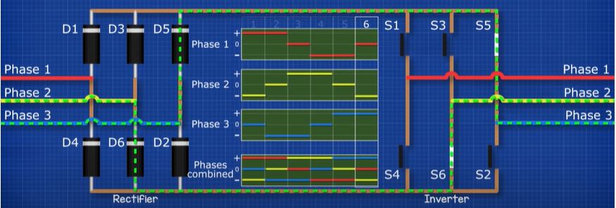
This cycle repeats again and again like so. If we check this with the oscilloscope, we will now have a wave pattern that looks something like AC, except it’s a little bit square. This will work fine for some applications but not all. So again we need to use pulse width modulation to create that sine wave. So we are going to use the controller to rapidly open and close the switches to vary the output frequency and voltage.


")

")

Well informed, detailed and concise Educating.
[…] We can convert AC to DC using a device known as a rectifier. This is extremely common in electronics. We can also convert DC to AC using an inverter and this is used, for example, with solar power systems. We have covered power inverters in great detail previously. Do check that out HERE. […]
Hi, This is my first time here. I have seen many videos, mainly Middle Eastern, that have a motor and an alternator with a flywheel. They state that it is self-running. But they only light a few light bulbs. A 20 HP motor is about 14.9 KW. Can I hook another motor to it and produce the 14.9 KW? What all would I need. As you can tell I am new to all this. But I am very interested in creating my own power. We have a lot of Hurricanes here in S.W. Florida. Power can be out for over a week. Thanks in advance.
Hi, am glad to have mate something like this as I never knew I could. Thanks alot for such a site and the dropped down content it’s really helpful.
Please I would love to join fully as is my wish to know most about electricity and its generation,
Thanks one again
[…] We have covered power inverters in great detail previously, you can read that HERE. […]