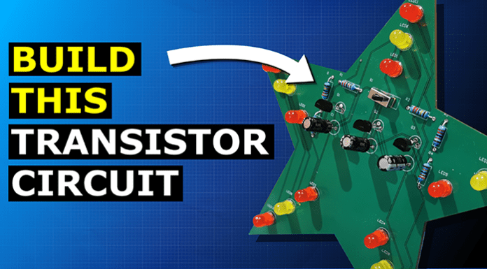
Transistors, capacitors, LED’s and resistors are all used in this simple festive circuit board decoration to automatically turn the lights on and off, in this pattern. I’m going to show you how the circuit works and how to build you own in this article and you can even download my circuit board design to build it yourself HERE.
Scroll to the bottom to watch the YouTube tutorial
How The Circuit Works
This circuit is based on something called an astable multi-vibrator or flip flop. A flip flop circuit simply turns the LED’s on and off alternatively. We can change how fast this occurs by changing the components.
We will need some transistors, which act as electronic switches. Basically they prevent current passing through them until a small amount of power is applied to the base pin.
You can see here that the LED circuit is connected across a transistor but it doesn’t turn on. It’s only when we apply a voltage and current to the base pin that the transistor allows the current to flow through the main circuit and turn the LED on. The transistor needs around 0.7V at the base pin to turn on.
We also need some capacitors, which basically charge up and store electrons when a battery is applied, but then release the electrons to power the circuit when the battery is removed.
You can see here that when I remove the power supply the LED turns off instantly, but when I connect a capacitor to the circuit, the capacitor powers the LED when the power supply is removed.
We can slow down the charging and discharging time of the capacitor by connecting it to a resistor. These limit the current which means they limit how many electrons can flow through the wire and therefore into or out of the capacitor in a certain amount of time.
Then we use some LED’s which basically produce light when electrons pass through them. These are very sensitive to current and will be destroyed if too many electrons are allowed to pass through them. So we need to connect a resistor to protect them. The resistor can also control how brightly they shine.
The circuit schematic for a simple flip-flop looks like this. Which we can then convert into a physical circuit using a breadboard and I highly recommend you try to build this yourself to help you understand how it works. When we connect a power supply, we see the circuit begins to flash the LED’s. So what’s happening here?
When we connect the power supply, the current is going to flow through resistor 3 and into the base pin of transistor 1, this will turn the transistor on and so a current can then flow through resistor 1 and LED 1. This causes electrons to be pulled into capacitor 1 through resistor 2 and build up on the right-hand side. When the voltage of capacitor 1 reaches 0.7 volts, this will open the base pin of transistor 2 and turn it on. This allows current to flow through resistor 4 and LED 2 which causes electrons to be pulled into capacitor 2 through resistor 3. This causes transistor 1 to turn off. When the voltage across capacitor 2 reaching 0.7 volts it turns transistor 1 on, and transistor 2 off. This then repeats constantly causing the LED’s to alternately turn on and off.
On our decoration, we have 3 different sets of LED’s, so we will modify this circuit to include another row. Capacitor 1 connects to transistor 2, capacitor 2 connects to transistor 3 and capacitor 3 connects back to transistor 1.
For the power supply we can’t use standard batteries because they are too big. We will instead use a 3 volt cell as these are compact. I’m going to use a Lithium CR2450 as these have a large energy capacity. We then need a switch to turn the circuit on and off.
The decoration needs multiple LED’s to turn on at the same time. We have 5 LED’s per transistor. As we only have a 3 volt supply, we can only use LED’s with low forward voltages such as RED and yellow. We will need to connect these in parallel so they all get the same voltage. If they were in series the voltage drop would be too much.
The forward voltage of the LED is around 1.8Volt and we have a 3Volt supply, so we need a resistor. We can place a resistor before each LED or we can use a single resistor to limit the total current. This is just a simple circuit so we can use a shared resistor.
As the voltage to an LED varies, the current and brightness change also. We don’t want the LED’s to shine too brightly as this will not look very good. So we will aim for around 10 milliamps per LED. As we have 5 LED’s we add these together to get 50 milliamps. 3 Volts from the battery subtract the 1.8 Volts of the LED, leaves us with 1.2 Volts which we need to remove. So, 1.2 Volts divided by the total current of 0.05 amps, equals 24 ohms. That means the resistor we need is 24 ohms. Now, I don’t have any 24 ohm resistors so I will use a 22 ohm resistor which will work fine for this application. The yellow LED will require a slightly higher resistor but the 22 ohm will work fine for this project.
Now for the transistor. We have two types the NPN and the PNP type. For this application we will require an NPN transistor. Most standard small transistors will work fine for this circuit, but I’m going to use the BC547 as this suits our voltages and current very well.
By the way we have covered how transistors work in detail in our previous article HERE.
Now, the capacitor and resistor are going to determine how fast the LED’s will flash. We could calculate this to get an approximate answer, but instead we’re going to plug components in and see what happens.
So if we use a 10 kilo ohm resistor and a 100 microfarad capacitor, we see the circuit works well. If I change this to a 1000 microfarad capacitor, the circuit is very, very slow. If I change it to a 10 microfarad capacitor, we see it is very fast. So the larger the capacitor, the slower the flashing will be.
The resistor also changes the charging time. If I use a 100 microfarad capacitor and a 10 kiloohm resistor it flashes quite fast. If we use a 47 kiloohm resistor we see it is very slow. If we use a 1 kiloohm resistor it flashes very, very fast. So the larger the resistor the slower the flashing. I’m going to use a 22 kiloohm resistor and a 100 microfard capacitor, because I think this works well and it looks very nice- and also, the capacitor is physically quite small.
So I’ve tested my design on a breadboard and we can see it is working well. Now to design the PCB.
Designing The Printed Circuit Board
Now to design the PCB we’re going to be using Altium designer, who have kindly sponsored this article. All of our viewers can get a free trial of the software HERE. So do check that out.
Ok so I’m going to give a quick walkthrough of this part, but we start a new project and then start to add our components in, there is an inbuilt feature for this but I’m using an addon, which makes it a little easier to simply import from a suppliers website. Luckily for this design, many of the components are the same so we can duplicate them and then arrange them. Then we start to connect the components together, connecting the LED’s, the capacitor, resistors, the power supply and also transistors and the switch too. So your schematic should look something like this. You’ll want to then configure the annotations also. Then, import the components to the PCB and define the board shape. Then place the components on the board in the order you wish until it looks like this. It’s important to place the LED’s in the correct order, group 1, group 2 and group 3. Then we will use auto route to connect everything together, but we must then inspect the board and make any modifications, if needed. After that, we create the polygon and finally we export the files.
So that’s the board designed, now we just need to order it and build it.
Manufacturing a PCB
To order the PCB we just head to JLC PCB .com who have also kindly sponsored this article. They offer exceptional value with 5 circuit boards from just 2 dollars HERE, do check them out. And don’t forget you can download my PCB file HERE. We then upload our gerber files and check the preview. It looks good. We can then change the colour of the board if we wanted to, but I’m leaving it green and then head to the checkout. I enter my shipping address, choose a postage option and then pay. A few days later my circuit board arrives in the post and they really look very good. So, we’re ready to now build the circuit.
Now that our circuit board has arrived we can start soldering the components to the board, it doesn’t take very long and then we should have something like this at the end. So, when I connect the power supply and switch the circuit on, we see the lights flashing in sequence. We can then display our decorative circuit board and admire our work. What do you think?

