

In this article, we’re going to learn what an inverter is and what it does. Understanding this information will help you understand the basics of electricity and how it works.
Scroll to the bottom to watch the YouTube tutorial.
A typical inverter looks something like this.
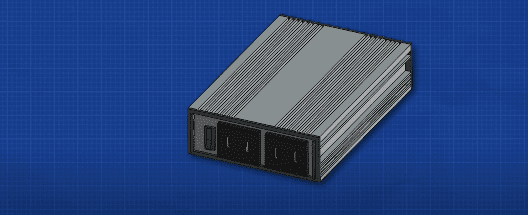
It has some red and black DC terminals on the back end and on the front end we find some AC electrical outlets. That’s because there are two types of electricity there. There is AC and there is DC. An inverter is used to convert DC or direct current into AC Alternating Current. We can also convert AC into DC with the use of a rectifier but we’ll cover that in a separate article HERE.
The appliances in our home are designed to run off an AC supply and they get that from the electrical outlets which all provide AC electricity. However, electricity produced by things such as solar panels and batteries produce DC electricity so if we want to power our electrical devices from renewable sources, battery banks or even our car then we need to convert DC electricity into AC electricity. And we do that with an inverter. The inverter consists of a number of electronic switches known as IGBT’s. The opening and closing of the switches is controlled by a controller. These can open and close super fast in pairs to control the flow of electricity by controlling the path which the electricity takes and how it flows in the different paths. We can produce AC electricity from the DC source.
I’m going to animate these using some simple switches to make them easier to visualise.
Remember AC is where the current reverses direction. We saw earlier in the article we can reverse the direction of current by reversing the battery. We could very quickly reverse the battery to produce a rough AC supply. But an easier way would be to connect four switches or IGBT’s across our load such as a lamp. If we open and close these in pairs. Then we can produce AC electricity. So if we were to close switches one and four, then the current flows in one direction. And if we open these and close switches 2 and 3, we get current flowing in the other direction. So we can use the controller to automatically do this again, and again and again.
If we did that 120 times per second then we would get 60 hertz electricity and if we did that 100 times per second then we would get 50 hertz electricity. As we have a low voltage input then we are going to get a low voltage output. To reach the 120 volts or 230 volts required to power our appliances, we also need a transformer to step up the voltage to a useful level. When we look at this through an oscilloscope, we get a square wave in the positive and negative regions. This is theoretically AC because it reverses direction, but it doesn’t really look much like an AC sine wave. So how can we improve this?
Pulse Width Modulation
Do you remember earlier in the article when I said we can open and close the switch at different speeds and duration to change the waveform? Well we can do that for this too. What we do is to use a controller to rapidly open and close the switches multiple times per cycle in a pulsating pattern. Each pulse varying in width. This is known as pulse width modulation. The cycle is broken up into multiple smaller segments. Each segment has a total amount of current that could flow but by rapidly pulsating the switches we control the amount of flow occurring per segment. This will result in an average current per segment which we see increases and decreases, thus giving us a wave. The load will therefore experience a sine wave. The more segments we have then the closer it mimics a smooth wave. We can control the output voltage by controlling how long the switches are closed for. So we could for example output 240 volts or 120 volts just by trimming the opening and closing times. We can also control the frequency by controlling the timing of the switches. So we could for example output 60 hertz, 50 hertz or 30 hertz, whatever is needed for the application. So that’s how we can take a 12 volt DC battery and convert this into a 120 volts or 230 volts AC supply by using some IGBTs, pulse width modulation and a transformer.


")

")
