
")
Learn the basics of an LED brightness dimmer controller. In this article we learn how to design and build a circuit to control the brightness of our LED strip lights. You can even build the circuit yourself!
Scroll to the bottom to watch the YouTube tutorial
This simple circuit allows us to dim LED strip lights and I’m going to show you how the circuit works, how to design one and even turn it into a professional looking printed circuit board. You can even download a copy of my circuit board and build your own HERE.
Design The Circuit
I’m going to be using SMD5050 LED strips which have a relatively low current demand and provide a good level of illumination. These are wired in parallel so we can cut them to a desired length, just ensure you cut along the marked cut line. I’m going to use 81 LED’s split into 9 strips of 9 LED’s.
To connect them we just cut some short lengths of wire and solder them, connecting the positive to positive and negative to negative. This will give us an LED panel.
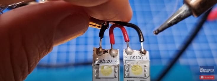
When we connect this to a DC power supply with 12 volts, we see it draws a current of approximately 1.3 Amps. As we reduce the voltage the lights become dimmer and the current also reduces.
We can use a switch to manually turn them on and off. But, we can instead use a mosfet, which is basically an electronic switch, to automate this and turn them on and off hundreds or even thousands of times per second, by simply applying a voltage to the gate pin.
I’m going to use an IRFZ44N mofet because it can handle the voltage and current and also has a low drain source ON resistance.
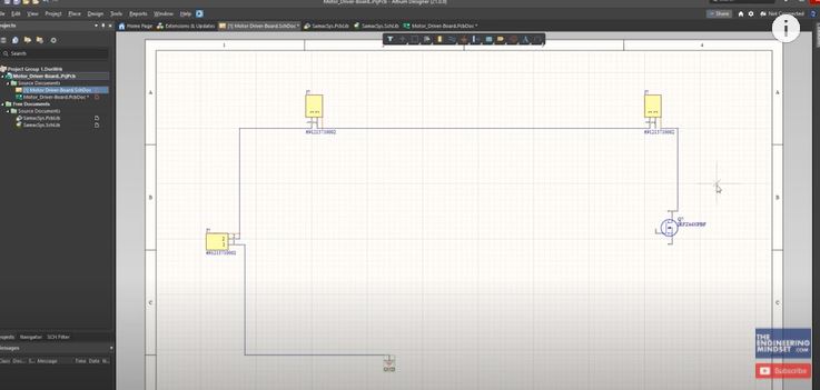
We’re going to be using Altium designer for this tutorial, who have kindly sponsored this article. All our viewers can get a free trial of this software HERE.
So, we start a new project and then start adding the components in. We find the components on a suppliers website, I’m using mouser but you can use whoever you wish. I’ve found the MOSFET so we take the part number and paste this into the library loader, which is an add-on, and we click search, it then finds the component so I click add to design.
I’m also going to add some terminal blocks, one for the power supply, one for a switch and another to connect the LED strip light. We connect the power supply terminal to ground, and then the positive terminal to the switch, then the switch output to the LED terminal. Then the LED return terminal will connect to the MOSFET drain pin. The mosfet source pin will then connect to ground.
To control the MOSFET we will use a pulse width modulation signal and we can use a simple 555 timer to achieve this. This is an integrated circuit which means inside it are a number of components added together to make a single component. That makes our job as a designer much easier. The component has 8 pins which are used for different purposes.
We find the component and add this to our circuit.
The mosfet will normally block the flow of current, but if we apply a voltage to the gate pin, it will allow current to flow so the LED illuminates. The higher the voltage applied, the more current is allowed to flow and the brighter the LED shines.
The 555 timer will provide the voltage to the mosfet, from pin 3. This will be sent in pulses. Each pulse lasts a period of time. During this period there will be a segment where the signal is on, so voltage is applied. And there will be a period where it is off, so no voltage is applied. The mosfet will therefor experience the average voltage for each time period. The wider the ON pulse, the higher the average voltage will be so the more current can flow through the mosfet and the LED will therefore shine brighter. This is pulse width modulation, because we are modulating the width of the pulse.
Coming back to the 555 timer.
Pin 8 is the components power supply, so we connect that to the positive track.
Pin 1 is the components ground. So we connect that to ground.
Pin 4 is also connected to the power supply, this is a reset pin. If the power to this pin is interrupted it will cause the 555 timer to reset. We don’t want that for this circuit so it is constantly powered.
Pin 5 is the control voltage pin which can be used to override the timer. We won’t use that for this circuit so we connect it to ground via a 0.1 micro farad ceramic capacitor. This prevents accidental override by filtering out noise or frequency.
Pin 3 is the output, which connects to the MOSFET. Normally only a very small current flows through here but if the MOSFET fails it could draw a high current and destroy the 555 timer. So, we place a 1 kilo Ohm resistor here to limit that and protect it. When the MOSFET is turned on, a small amount of electrons are stored inside, we need to discharge these to turn the mosfet off. So we place a 10kOhm resistor after the 1 kiloohm and connect this to ground. This allows the mosfet to discharge to ground. We could use a smaller resistor also but this will work fine.
Inside the 555 timer we have three, 5 kilo Ohm resistors in series between pin 8 and pin 1. We have around 12V from the power supply at pin 8. Each resistor drops one third of the voltage. So here we get 8 volts and here we get 4 volts. These will be used as a reference.
Connected to the resistors are two comparators. The comparator has a positive and negative input as well as a single output. The first comparator is connected to the resistors through the negative input. The positive input is connected to pin 6, the threshold pin. Comparator 2 is connected to the resistors via the positive input. Its negative input is connected to pin 2, the trigger pin.
The comparator is now connected across two different voltages, so it can compare them. If the positive input voltage is higher than the negative input, it outputs a high signal or positive voltage. If the negative input voltage is equal to or higher than the positive input voltage, it will output a low signal or zero voltage.
We will connect pin 2 and 6 together so that the voltage is the same. The output from the comparators connect to another internal component called the flipflop.
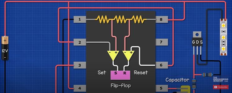
The first comparator connects to the input called “reset”, the second comparator connects to the input named “set”. There is also an output named “not Q”. When the flipflop receives a high signal from comparator 1, it outputs a high signal. When the flipflop receives a high signal from comparator 2, it outputs a low signal. If both comparators provide a low signal, the flipflop remains unchanged and continues. This will then pass through another component called an inverter, which simply inverts the signal it is given.
If we apply a small voltage of say 3.9V to pins 2 and 6, comparator 1 outputs a low signal, and comparator 2 outputs a high signal. This sets the timing interval to begin. The Flipflop outputs a Low signal. The inverter outputs a high signal.
As we increase the voltage, for example to 6 volts. Comparator 1 and 2 will output a low signal, the flipflop remains unchanged, the timing continues. But, at 8 volts, comparator 1 outputs a high signal, and comparator 2 outputs a low signal. The output of the flipflop now reverses and the output is high. This resets the timing.
The output of the flipflop remains the same until the voltage decreases to around 4 volts, where comparator 1 outputs a low signal and comparator 2 outputs a high signal, this starts the timer again.
So, we see that as the voltage on pins 2 and 6 increases and decreases, the output of the 555 timer changes. So, to control the voltage and therefore the time interval, we connect pins 2 and 6 to a capacitor.
When we connect a capacitor to a power supply, it instantly reaches the battery voltage. But if we connect it via a resistor, the resistor slows down the charging time. The larger the resistor, the longer it takes to increase the stored voltage.
So to charge our capacitor we will use a fixed 1 kiloohm resistor and a 100 kiloohm potentiometer. The potentiometer is a variable resistor so we can therefore vary the capacitor charging time. We will need to also discharge the capacitor in order to restart the timer. So, we will add two diodes to create a separate charge and discharge path. The current in this part of the circuit is very small since the resistors are in the kiloohm range. We will use two 1N4148 diodes, which have a forward current of around 300 miliAmps which will be fine for this application.
The capacitor will be a 10 nano farad ceramic capacitor, we will see why in just a moment. So we add these components to the circuit, then connect the diodes to the fixed resistor, and the diodes to pins 1 and 3 of the potentiometer. Then we connect the capacitor to ground as well as to pin 2 and 6 of the 555 timer and also to pin 2 of the potentiometer.
Pin 7 is the discharge pin, which is connected to our timing capacitor. Inside the 555 timer, the output of the flipflop connects to the gate pin of an internal transistor.
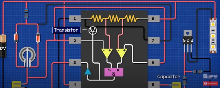
This controls the flow of current from the capacitor to ground. When the flipflop output is low, the transistor is off, so the capacitor charges and the voltage begins to increase. When the voltage increases enough so that the output of the flipflop is high, the transistor is turned on which discharges the capacitor and so the voltage reduces. When it reaches 4V, the capacitor begins to charge again, when it reaches 8V it will discharge.
Ok, so when charging the current flows through the resistor, diode and left side of the potentiometer, to the capacitor. The flipflip output is low so the discharge transistor is off. Pin 3 outputs a high signal.
Once the capacitor charges to 8V, the flipflop output becomes high, which turns the transistor on and the capacitor discharges through the right side of the potentiometer and diode. Pin 3 outputs a low signal.
The transistor remains open so the capacitor discharges until it reaches 4V where the flipflop reverses again, turning the transistor off, which starts the timing again. This cycle repeats continuously. The capacitor charges and discharges creating a saw tooth wave and the 555 timer outputs a square wave, which is pulse width modulated.
We used a 10 nano farad capacitor, but we don’t necessarily have to. If we use these formulas to calculate the charge and discharge times with the potentiometer at 50%. We see each cycle is around 0.69 miliseconds which gives us a frequency of 1.4 kilo hertz. The human eye can detect lights flickering at low frequencies. The standard lights in your home are usually 50 to 60 Hertz, and we are operating at much higher frequency so we can use a larger capacitor to decrease this.
But if we used for example a 100 microfarad capacitor the frequency would be 0.14 Hertz and each cycle would take 7 seconds to complete which would be pretty useless. So, consider how it will impact your design.
Ok, so I build a simple prototype to check it all works. It seems to be fine and I an adjust the brightness so we will finish he PCB design.
We import the components to the PCB design file and spend some time arranging these around the board. We then define the board shape and add any annotations. Then generate the route to connect everything. Then we increase the track width for the higher voltage and current areas of the circuit and also check the routes and move them if needed. Once satisfied we can create the polygon and export our gerber files.
Manufacturing The PCB
So now we’re ready to have our circuit board printed.
We’re going to be using JLC PCB to print our circuit board, who have also kindly sponsored this article They offer exceptional value with 5 circuits boards from just $2. Do check them out HERE.
Don’t forget you can download my design files HERE.
So, we simply login and then upload our gerber file. After a few seconds it generates a preview of the circuit on screen. We can then customise the design with different colours and materials etc. But I’ll leave these as default and save it to cart. Then we head to the checkout, fill out our postage details, and then select the postage option. I want this very fast so I select the express postage which is more expensive, you can choose the slower methods to save on costs. Then we submit the order and pay.
A few days later our circuit board arrives in the post. The boards look great, I’m very happy with the result.
So, we start soldering the components to the board. I start from the centre and work my way outwards. Some of the components are tricky so we use some tape to hold them in place. And after a few minutes we should have a perfect looking circuit board.
Now for the test. We connect the lights to the terminal as well as the power supply. I flip the switch to power the circuit board on and then as I adjust the potentiometer the lights will increase and decrease in brightness.


")

")

is it wrong to say you could just hook up the potentiometer directly to the current by itself since it would increase or decrease resistance against the flow anyway? maybe im looking at it wrong?
Hello, All the PWM controllers work on the ground side and i’m trying to make something that controls the positive side. Because I want to use it for automotive dash light dimmer, but the ground is common on the dash for other things too so I need the control side to be on the positive. I’m having trouble wrapping my brain around n-channel and p channel transistors. Can you help me?
I have this same question. I wish someone would post a circuit that connects/controls the positive side of the led’s.