

Learn how the electrical motor works, the main parts, why and where they are used along with worked examples.
Scroll to the bottom to watch the YouTube tutorial
This is an electrical motor. It’s one of the most important devices ever to be invented. These motors are used everywhere from pumping the water we drink, to powering elevators and cranes, even cooling nuclear power stations. So, we’re going to look inside one and learn in detail, exactly how they work in this article.
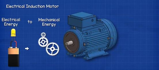
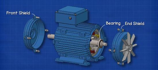
The induction motor will look something like this. They turn electrical energy into mechanical energy, which we can use to drive pumps, fans, compressors, gears, pulleys etc. Almost all the parts are held inside the main housing. At the front we find the shaft, this is the part that rotates and we can connect things like pumps, gears and pulleys to this, to do work for us. At the back we find the fan and a protective cover, the fan is connected to the shaft, and so it rotates whenever the motor operates. The induction motor can produce a lot of heat when in operation, so the fan blows ambient air over the casing to cool it down. If the induction motor becomes too hot, the insulation of the internal electrical coils will melt, causing a short circuit and the motor will destroy itself. The fins on the side of the enclosure help to increase the surface area and that lets us remove more unwanted heat.
The shaft is supported by some bearings which sit inside the front and rear shields. The bearings help the shaft rotate smoothly and hold it in position.
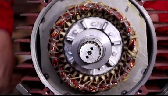
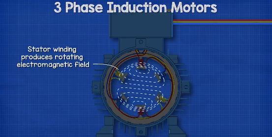
Inside the housing we find the stator. The stator is stationary and does not rotate. This consists of a number of copper wires which are wrapped into coils between the slots positioned around the inner perimeter. The copper wire is coated with a special enamel which electrically insulates the wires from each other, this means electricity has to flow through the entire coil, otherwise it would take the shortest path possible – and we’ll see why that’s important a little later in this article. This is a three-phase induction motor, so we have three separated sets of coils in the stator. The ends of each set will connect to the terminals within the electrical terminal box. We’ll see how these are connected a little later in this article. When connected to the electrical supply, the stator generates a rotating electromagnetic field.
Connected to the shaft is the rotor. In this case it’s a squirrel cage type rotor. It’s called a squirrel cage because it has two end rings which are connected by some bars, and these rotate together. This design is similar to a small cage or exercise wheel used by a pet hamster or even a squirrel.
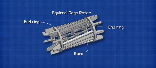
The squirrel cage is fitted with a number of laminated steel sheets. These sheets will help concentrate the magnetic field to the bars. Sheets are used instead of a solid piece of metal as this improves efficiency by reducing the size of eddy currents in the rotor.
When the rotor is placed inside the stator and the stator is connected to an electrical power supply, the rotor will begin to rotate. So, how is this possible?
How Induction Motors Work
When electricity passes through a wire, an electromagnetic field is generated around the wire. We can see this by placing some compasses around the wire, the compasses will rotate to align with this magnetic field. If the direction of current is reversed, the magnetic field reverses also, so the compasses change direction.
The magnetic field of the wire is pulling and pushing the compass dials. Just like if we slide two bar magnets towards each other. They will either be attracted or repelled. We can even use one magnet to rotate another magnet. Or, we can rotate the magnet by changing the intensity of the magnetic field around it.
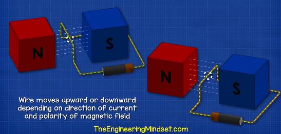
If we place a wire in a magnetic field and pass a current through it, the magnetic field of the wire will interact with the permanent magnets, magnetic field and the wire will experience a force. This force will move the wire either upwards or downwards, depending on the direction of current and the polarity of the magnetic fields.
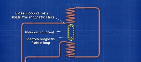
If we wrap the wire into a coil, the electromagnetic field becomes stronger, the coil will produce a north and south pole just like a permanent magnet. We call these coils of wire an inductor. When we pass alternating current through the wire, the electrons will be constantly changing direction between flowing forwards and backwards. So, the magnetic field will also expand and collapse and the polarity reverses each time. When we place another, separated, coil in close proximity and complete the circuit, the electromagnetic field will induce a current in this second coil.
We can connect two coils together and place them opposite each other to create a larger magnetic field. If we place a closed loop of wire inside this large magnetic field, we will induce a current in the loop. As we know, when we pass a current through a wire, it generates a magnetic field and we also know that magnetic fields will push or pull each other. So, this loop of wire will also generate a magnetic field and this will interact with the larger magnetic field. Each side of the coil will experience opposing forces, causing it to rotate. This loop is therefore our rotor, and the coils are the stator.
The rotor will only rotate until it aligns with the stator coils though, then it will get stuck as the induced current reverses with the coil. To overcome this, we need to introduce another set of coils in the stator, and we must connect these to another phase. The electrons flow in this phase at a slightly different time, so the electromagnetic field will also therefore change in strength and polarity at a slightly different time. This will force the rotor to rotate.
Inside the induction motor we have 3 separated coils which are used to produce a rotational electromagnetic field. When we pass an alternating current through each coil, the coils will produce an electromagnetic field which changes in intensity as well as polarity as the electrons change direction, but, if we were to connect each coil to a different phase, then the electrons in each coil will change direction at a different time. This means the polarity and intensity of the magnetic field will also occur at a different time.
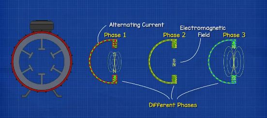
To distribute this magnetic field we need to rotate the coil sets 120 degrees from the previous phase, and then combine these into the stator. The magnetic field varies in strength and polarity between the coils which combine to produce the effect of a rotating magnetic field.
We saw earlier in this article that current can be induced into a second coil, when in close proximity. The bars of the squirrel cage are shorted at each end which therefore creates multiple loops or coils, each bar therefore induces a current and creates a magnetic field.
The magnetic field of the rotor bars interacts with the magnetic field of the stator. The rotor bars magnetic field is attracted to the magnetic field of the stator. As the magnetic field is rotating, the rotor will therefore also rotate in the same direction as the magnetic field to try and align with it, but it will never be able to fully catch up.
The bars of the rotor are often skewed. This helps distribute the magnetic field across multiple bars and stops the motor being able to align and jam.
Electrical Connections
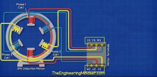
The stator contains all the coils or windings used to create the rotating electromagnetic field when electricity is passed through the wires. To power the coils, we find an electrical terminal box on the top, or sometimes on the side.
Inside this box we have 6 electrical terminals. Each terminal has a corresponding letter and number, we have U1, V1 and W1 then W2, U2 and V2. We have our phase one coil connected to the two U terminals, then the phase 2 coils connected to the two V terminals and lastly the phase 3 coil connected to the two W terminals. Notice that the electrical terminals are arranged in a different configuration on one side to the other. We’ll see why that is in just a moment.
We now bring in our three-phase power supply and connect these to their respective terminals. For the motor to run we need to complete the circuit and there are two ways to do this. The first way is the delta configuration. For this we connect across the terminals from U1 to W2, V1 to U2 and W1 to V2. This will give us our delta configuration.
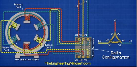
Now, when we provide AC current through the phases, we see that electricity flows from one phase to another as the direction of ac power reverses in each phase at a different time. That’s why we have the terminals in different arrangements in the terminal box, because we can easily connect across and allow electricity to flow between the phases as the electrons reverse at different times.
The other way we can connect the terminals is to use the star, or wye, configuration. In this method we connect between W2, U2 and V2 on only one side. This will give us our star or wye equivalent connection. Now, when we pass electricity through the phases, we see the electrons are shared between the terminals of the phases.
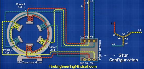
Due to their design differences, the amount of current flowing in the star and delta configuration is different, and we will see some calculations for these towards the end of the article.
Star (Wye) Delta Calculations
Lets have a look at the difference between star and delta configurations.
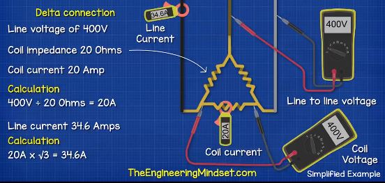
Let’s say we have the motor connected in delta, with a supply voltage of 400Volts. That means when we use a multimeter to measure the voltage between any two phases, we will get a reading of 400Volts, we call this a line to line voltage.
Now if we measure across the two ends of a coil, we again see the line to line voltage of 400Volts. Lets say each coil has a resistance or, impedance as this is alternating current, of 20 Ohms. That means we will get a current reading on the coil of 20 amps. We can calculate that from 400Volts divided by 20 Ohms which is 20 Amps. But, the current in the line will be different, it will be 34.6Amps. We get that from 20Amps multiplied by the square root of 3 which is 34.6Amps, that’s because each phase is connected to two coils.
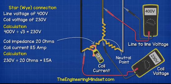
Now if we look at the star or wye configuration, we again have a line to line voltage of 400V. We see that, if we measure between any two phases. But, with the star configuration, all our coils are connected together and meet at the star point or the neutral point. It’s from this point we can run a neutral wire if we need to. So, this time when we measure the voltage across the ends of any coil, we get a lower value of 230Volts, that’s because the phase isn’t directly connected to two coils like in the delta configuration, one end of the coil is connected to a phase but the other is connected to the shared point, so the voltage is therefore shared. The voltage is less as one phase is always in reverse. We can calculate this by 400Volts divided by square root of 3 which is 230Volts. As the voltage is less, the current will be too. If this coil also has an impedance of 20 Ohms, then 230Volts divided by 20Amps =11.5Amps. The line current will also therefore be the same at 11.5Amps.
So we can see from the delta configuration, the coil is exposed to the full 400V between two phases, but the start configuration is only exposed to 230V between the phase and neutral point. So the star uses less voltage and less current compared to the delta version.


")


")

")