

Learn about the full wave bridge rectifier, the half wave rectifier the full wave rectifier, center tapped transformers, diodes, load, oscilloscope, waveform, DC, AC, voltage current, capacitors, bleeder resistor to learn how full wave bridge rectifiers work.
Scroll to the bottom to watch the YouTube tutorial.
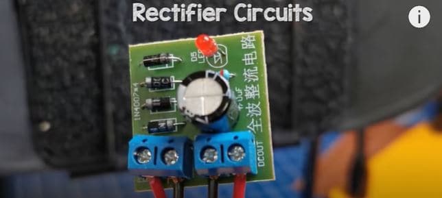
This is a full wave bridge rectifier. It’s used to power our electronic circuits, so we’re going to learn in detail how they work in this article.
Electricity is dangerous and can be fatal, you must be qualified and competent to carry out any electrical work.
What is a Full Bridge Rectifier
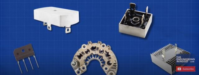
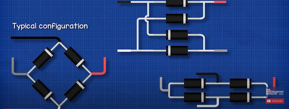
Full bridge rectifiers look like this, there are many shapes and sizes but they essentially consist of 4 diodes in a certain arrangement. They are usually aligned in a Diamond configuration, but they can also be aligned in other ways such as these.
We typically find them represented on engineering drawings like this.
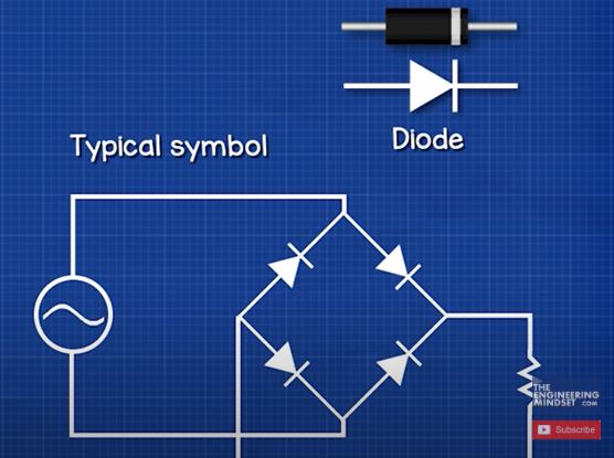
This being the symbol for a diode. The arrow points in the direction of conventional current. This is showing that AC electricity is the input and DC electricity is the output.
The full bridge rectifier converts AC alternating current, into DC direct current. Why is that important? Because the power outlets in our homes provide AC but our electronic devices use DC, so we need to convert the AC into DC electricity.
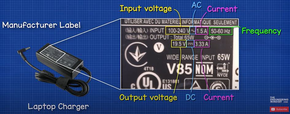
For example, a laptop charger takes AC from the power outlet and converts this to DC to power the laptop. If you look at the power adapter for your laptop and electronic devices, the manufacturers label tells you it’s converting AC to DC. In this example it states it needs an input of between 100 and 240V, with the symbol for AC electricity, and it will draw 1.5Amps of current. It will then output 19.5V of DC electricity and 3.33 Amps of current. Notice it also states 50-60 Hz, this is the AC frequency and we’ll look at that in just a moment.
In AC electricity the voltage and current constantly change direction between forwards and backwards. That’s because there’s a magnetic field in the AC generator which essentially pushes and pulls the electrons in the wires. This is therefore changing between positive and negative values as it flows forwards and backwards, the voltage is not constant, even though the multimeter makes it look like it is. If we plotted this, we get a sine wave pattern. The voltage changes between a peak positive and peak negative value as the maximum intensity of the magnetic field passes the coils of wire.
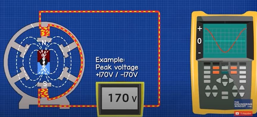
This example reaches 170V at its peaks, so if we plotted these values we have positive and negative peaks of 170V. If we took the average of these values we get zero volts. That’s not very useful, so a clever engineer decided to use the root mean squared voltage. That is what our multimeters calculate when we connect them to the electrical outlets.
To find the peak voltage, we multiply the RMS voltage by the square root of 2 which is roughly 1.41.
To find the RMS voltage we divide the peak voltage by 0.707.
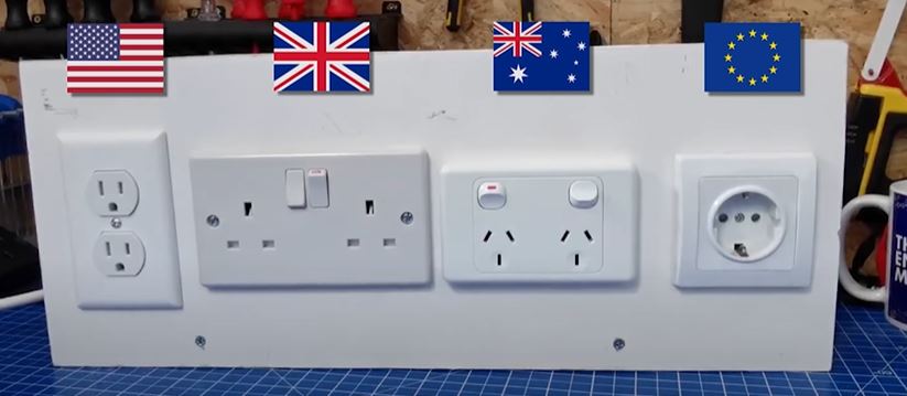
For example here I have a North American, British, Australian and European power outlet. This multimeter shows basic wave forms and when I connect to any of these between the phase and neutral, we see a sine wave, indicting it is AC electricity. Notice that the British and European outlets are 230V, the Australian is 240V but all three are at a frequency of 50 Hz, however the north American outlet reads 120V at a frequency of 60Hz.
The frequency is measured in Hertz but this just means the sine wave is repeating 60 times per second in the north American electrical systems and 50 times per second in the rest of the world. The voltage is lower in the north American system at 120V where as it’s 230-240V in the rest of the world. The peak voltage of each electrical system is therefore as follows.
In DC electricity the voltage is constant and in the positive region, the electrons do not reverse they all flow in just one direction. So, if I measure this battery, we see a flat line in the positive region at around 1.5V so this is DC electricity.
This solar panel also produces DC, we can see it produces a flat line at around 4V on the multimeter. We can use this adapter to measure a USB port, we can see it’s providing around 5V and if we plot this with the other multimeter, we again see a constant flat line indicating it is DC electricity.
This is a full wave bridge rectifier. On these input terminals we see around 12V AC with a sine wave. And on these output terminals we see around 14V of DC. So this device is converting AC to DC. The voltage is slightly higher because of the capacitor, and we’ll see why that is later in this video.
This only converts AC to DC, it will not convert DC to AC. For that we need an inverter, which uses special electronic components to achieve that but we won’t cover that in this article.
By the way we have covered how power inverters work in detail in our previous article, check that out HERE.
How It Works
The rectifier consists of diodes. A diode is a semiconductor device which allows current to flow through it, but, in only one direction. So, if we connect this lamp to a DC power supply, it will illuminate. We can reverse the leads and it will still illuminate. If I place a diode on the red wire, and connect this to the positive, it will again illuminate. But now, when I reverse the leads, the diode blocks the current and the lamp remains off. So, it only allows current to flow in one direction and we can use this to control the direction of current in a circuit to form DC electricity.
Half Wave Rectifier
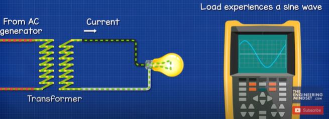
If we looked at an AC supply, with a step down transformer which reduces the voltage, the electrons are flowing forward and backwards. So, the load experiences a sine wave. The load could be anything from a resistor, a lamp, a motor etc.
If we inserted a diode, the diode will only allow current to flow in one direction, so the load now experiences a pulsating wave form. The negative half of the sine wave is blocked. We can reverse the diode to block the positive half and only allow the negative half. This is therefore a half wave rectifier. The output is technically DC, because the electrons only flow in one direction, it’s just not a very good DC output as it is not completely flat.
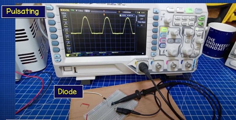
Here, I have a resistor which is connected to a low voltage AC supply. We see on the osciliscope, the AC sine wave. When I connect a diode in series with this, the osciliscope shows a pulsating pattern in the positive region. If I reverse the diode, the osciliscope shows a pulsating pattern in the negative region.
If I connect two lamps in parallel, one with a diode, we see the one without the diode is brighter because it’s using the full wave form. The other lamp is dimmer because it’s only using half of this. If we view this in slow motion, we see the diode connected lamp is flickering more because of the gaps in power.
Therefore we can use this for simple circuits such as lighting, or charging some batteries but we can’t use it for electronics as the components need constant power, otherwise they will not work correctly.
We can add a capacitor in parallel with the load to improve this output. We’ll look at that later in this article. A better improvement is to use a full wave rectifier, and there are two main ways to do that.
Full Wave Rectifier
We can create a full wave rectifier simply by using a centre tapped transformer and two diodes. A centre tapped transformer just has another wire on the secondary side, which is connected to the centre of the transformer coil, allowing us to use the full length of the transformer or just half of it.
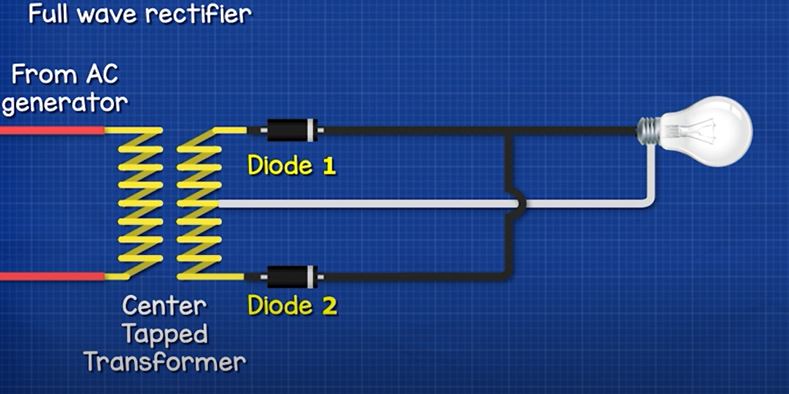
Because the current constantly reverses in AC electricity, while in the positive or forward half, the current flows through diode 1 and into the load, then back to the transformer via the centre tapped wire. Diode 2 is blocking the current so it can’t return through here. Only half the transformer coil is therefore used. In the reverse or negative half, the current flows through diode 2, through the load and then back to the transformer. Diode 1 is blocking the current.
The current flows in one direction through the load, so it is considered DC, but it is still pulsating, although there are no gaps. The negative half has been converted into a positive half. The waveform is not smooth, so we need to apply some filtering, such as a capacitor. We’ll look at that in detail, later in this article.
Full Wave Bridge Rectifier
The most common method used is the full wave bridge rectifier. This uses 4 diodes. The AC supply is connected between diodes 1 and 2, with the neutral between 3 and 4. The DC positive output is connected between diodes 2 and 3, and the negative between diodes 1 and 4.
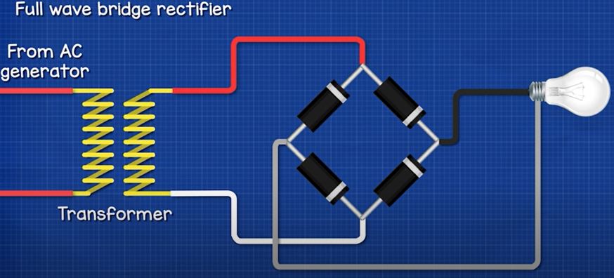
In the positive half of the sine wave, the current flows through diode 1, through the load, through diode 2 and then back to the transformer. In the negative half, the current flows through diode 3, though the load, through diode 1 and back to the transformer. So the transformer is supplying an AC sine wave, but the load is experiencing a rippled DC wave form because the current flows in one direction.
In this circuit here we can see that rectified waveform on the oscilloscope. But it is not a flat DC output, so we need to improve this by adding filtering.
Filtering
Using a rectifier will result in a ripple in the wave form. To smooth this out we need to add some filters.
The basic method is to simply add an electrolytic capacitor in parallel to the load. The capacitor charges during the increase in voltage and stores electrons. It then releases them during the decrease, this therefore reduces the ripple. The oscilloscope will show the peaks of each pulse, but now the voltage doesn’t decrease to zero, it slowly declines until the pulse charges the capacitor again. We can further reduce this by using a larger capacitor or by using multiple capacitors.
In this simple example you can see the LED turns off, as soon as the power is interrupted. But, if I place a capacitor in parallel with the LED, it remains on because now the capacitor is discharging and powering the LED.
In this circuit I have a lamp connected as the load. The oscilloscope shows the rippled waveform. When I add a small 10 microfarrad capacitor, we see it makes very little difference to the waveform. When I use a 100 microfarrad capacitor we see the dip is no longer down to zero volts. At 1000 microfarrads the ripple is very small. At 2200 microfarrads it’s nearly completely smooth, this would be fine to use for many circuits though. We could use multiple capacitors also, here we have a 470 microfarrad capacitor which has made some difference, but if I use two capacitors in parallel, we see the wave form is much improved.
When using a capacitor we need to place a bleeder resistor across the output. This is a high value resistor which will drain the capacitor when the circuit is off to keep us safe. Notice with this circuit, when I switch it on, the capacitor charges quickly to over 15V. When I switch it off, the DC output is still at 15V because there is no load, so the energy is still stored. This could be dangerous if the voltage is high. In this example I place a 4.7kohm resistor across the output, we see the capacitor charges up to 15V, and when I switch it off, the capacitor quickly discharges. The electrons are flowing through the resistor which discharges the capacitor.
We also see that without a capacitor, the output voltage is lower than the input voltage because of the voltage drop of the diodes.
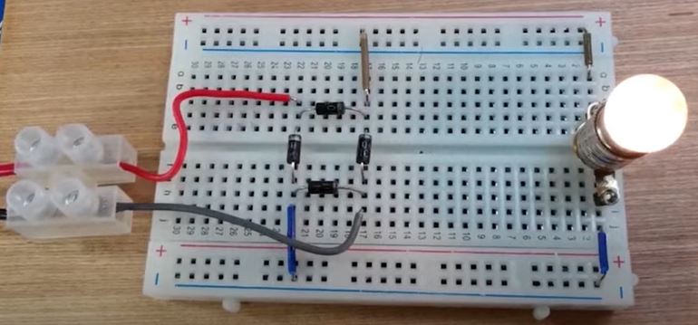
Here we have a simple full wave bridge rectifier. On the input we see there is 12V AC, on the output we have 10.5V of DC. The voltage on the output is lower because of the diodes. Each diode has a voltage drop of around 0.7V. If we look at this circuit, with a diode and an LED. We can measure across the diode to see a voltage drop of around 0.7V. The current in our full bridge rectifier must pass through 2 diodes on the positive half and 2 on the negative half. So, the voltage drop combines and is around 1.4 to 1.5V. So the output is reduced.
However, if we connect a capacitor across the output, we see the output voltage is now higher than the input voltage. How is that possible? That’s because the AC input is measuring the RMS voltage, not the peak voltage. The Peak voltage is 1.41 times higher than the RMS voltage. The capacitors are charged up to the peak voltage and then release. There is still a small voltage drop because of the diodes so the output is less than the peak input, but it will still be higher than the RMS input.
For example, if we had 12Vrms on the input, the peak voltage would be 12V multiplied by 1.41 which is 16.9V
There’s 0.7v drop here and here. So 16.9 subtract 1.4V is 15.5V. The capacitors are charged up to this voltage. This is only the approximate answer, the amount of ripple and the actual voltage drop of the diodes will cause it to be slightly different in reality, but we can see the output is higher than the input.
Another common filter is placing two capacitors in parallel with a series inductor between these. This is used for circuits with larger loads. The first capacitor smooths the ripple. The inductor opposes the change in current and tries to keep it constant and the second capacitor, which is much smaller, will then smooth out the final remaining ripple.
Additionally, we can also connect a voltage regulator to the output. This is very common and allows some variation on the input, but will provide a constant output voltage. This again has capacitors on either side of the regulator to ensure a smooth DC output. Here’s a real version which is connected to a 12V ac supply and we see it has an output of around 5V DC.
You can learn to build your own voltage regulator in our previous article HERE.


")

")
FULL BRIDGE RECITIFERRRRRR!
I also doesn’t know you have a website!1