

Learn how to build a basic centrifugal pump and also test the blade designs using computational fluid dynamics. You can also download the PDF templates for this pump HERE.
SimScale provides instant access to computational fluid dynamics (CFD) as well as finite element analysis (FEA) to over 200,000 users. SimScale has moved high-fidelity physics simulation technology from a complex and cost-prohibitive desktop application to a user-friendly cloud application accessible via a subscription-based pricing model.
Try for SimScale free:➡️ https://bit.ly/2N9Ugmt
As it is cloud-based, no installation is required, just sign up on the website for a free community account before purchasing a yearly plan. See pricing:➡️ https://bit.ly/2BnbHNA CFD and FEA webinars on HVAC, industrial & turbomachinery:➡️ https://bit.ly/3diSiuD SimScale Blog on industry applications and design tips ➡️ https://bit.ly/3ddwtwx
SimScale tutorial:➡️ https://bit.ly/2Yhws6A
Scroll to the bottom to watch the YouTube tutorial.
How To Make The Pump
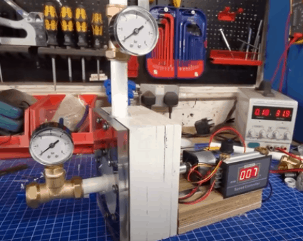
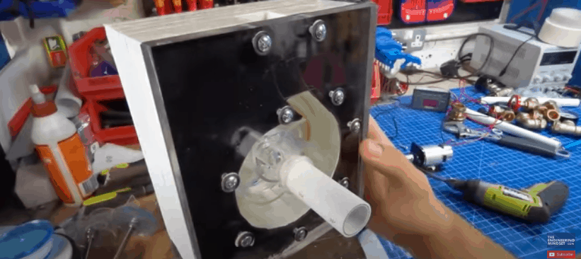
This is the pump we built. It’s a centrifugal type pump made mostly from wood and plastic and it’s driven by a DC motor with a pulse width modulation speed controller. We then ran the pump at various speeds to see how it performed.

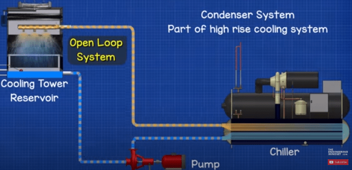
As you can see, this pump is being used in an open loop system, circulating water between a reservoir, the pump and then back into the same reservoir. This is a similar setup to the condenser side of a water-cooled chiller, which is used to provide large scale air conditioning to high rise commercial buildings. The water is pushed through the heat exchanger of the chiller to pickup the unwanted heat from the building and this is then sent up to the cooling tower on the roof, the water is sprayed to release the heat into the atmosphere and the now cooler water then collects in the pan of the cooling tower and cycles back down to the chiller to pick up more heat.
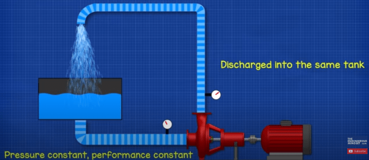
By using this system, we maintain the same suction pressure on the pump inlet.
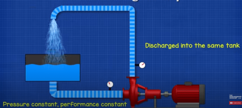
If the pump discharged into a separate tank, the water level at the inlet will change and so will the pressure, resulting in the pumps performance varying. To combat this, we would need to top-up the same quantity of water that was removed. So, it’s therefore easier to loop the water back into the same tank.
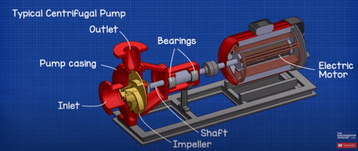
A centrifugal pump is fairly simple and has only a few parts. The main ones being the pump casing. The impeller. The shaft. The inlet and outlet. Some bearings and an electric motor.
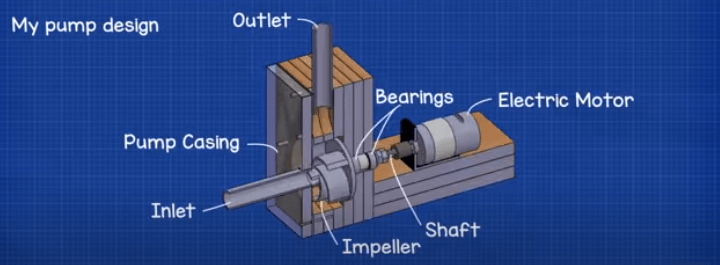
Our design looks like this. We have the pump casing, the impeller and shaft. The bearing house. The inlet and out and an electric DC motor.
The Pump Design
To keep the design simple, we decided to use materials that were readily available. For the pump casing we used marine plywood, this is a strong material that’s formed with a waterproof glue, it’s easy to work with and is often used to build boats. We wanted to be able to see inside the pump as it rotates so we decided to use a thick sheet of acrylic with a rubber seal between this and the pump casing. For the impeller we again used acrylic because it’s easy to work with and can be fused together with a solvent to form a strong joint. The shaft is made from stainless steel threaded rod with stainless locking nuts. We used stainless steel because the impeller will be submerged in water and stainless steel is harder to rust compared to mild steel. The pipes were made from PVC because it is cheap and has a very low friction factor. The fittings were mostly made from copper simply because that’s what our local store had in stock. To drive the pump, we used a 775 DC motor with a variable speed drive.
Parts Used
PWM Speed control: http://engineerz.club/pwm-speed-control
775 Motor: http://engineerz.club/775-motor
Motor Coupling: http://engineerz.club/dc-motor-coupling
Threaded rod: M8 Stainless Steel Threaded Rod
Wood: 12mm Marine Plywood
Acrylic sheet: 12mm http://engmind.info/acrylic-sheet
DC Supply: http://electricl.info/DC-Bench-Power-…
Water Cup: https://amzn.to/2NcnMIh
Pipe: 22mm Barrier Pipe PVC
Seal: 2mm black Rubber
Blade tube: 50mm OD Acrylic tube
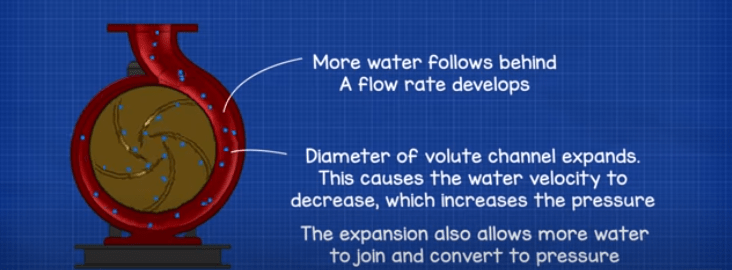
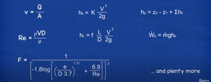
Now that we had selected the materials, we just needed to design the pump. Centrifugal pumps use a volute, which is an expanding channel around the impeller that converts water velocity into pressure as well as allowing a flow rate to develop.
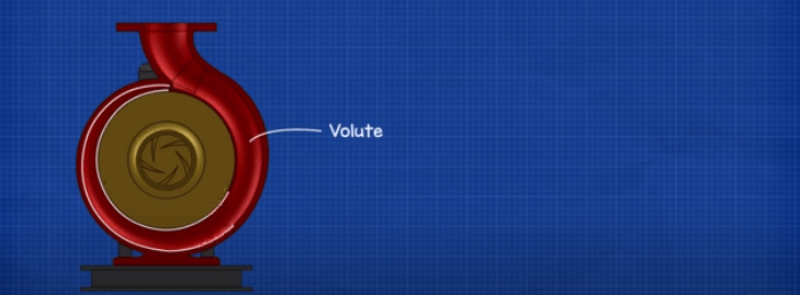
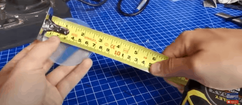
We already had some 70mm discs for the impeller so we based our volute around this and sketched a rough volute shape out in CAD.

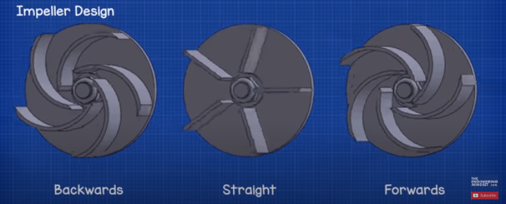
To design the blades of the impeller we have 3 main options. The blades can either be backwards curved, straight or forwards curved. To keep the design simple to build, we decided to use segments of 50mm acrylic pipe to form the curves of the blades. The dimensions of the pipe mean we can only really fit 5 blades onto the impeller. We just used the inverse of this design for the forwards curve impeller. For the straight design we’ll also use 5 blades made from a thin sheet of acrylic.
Assessing Performance of Each Pump Impeller Design
To assess the performance of each pump impeller design, we’ve utilised the SimScale CAE platform, who have kindly sponsored this video. SimScale provides instant access to online computational fluid dynamics as well as finite element analysis via a user-friendly cloud-based application available through a simple subscription model. You can try the software for free and edit public projects at simscale.com via their community account, or you create private projects with enhanced features via their professional, team or enterprise accounts. If you want to try this software out yourself click HERE.
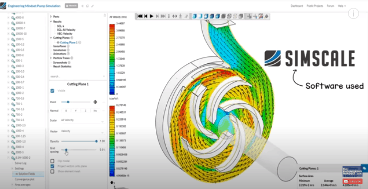
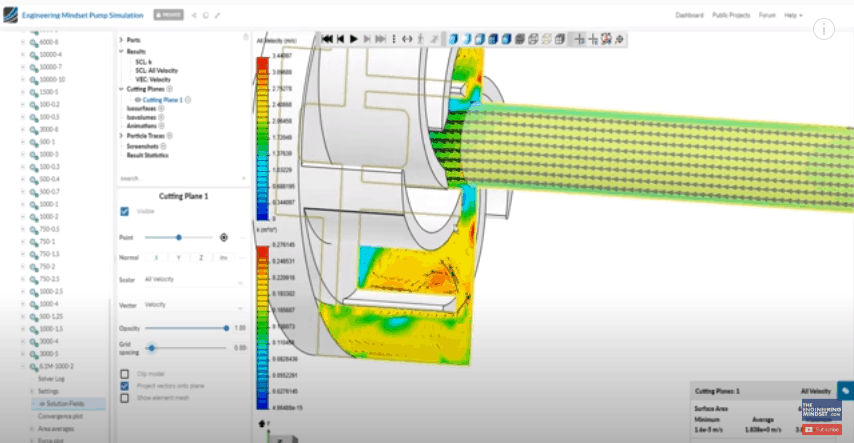
So, after we designed the pump casing and the different impeller designs in CAD, these are then imported into SimScale for analysis. We don’t know all the parameters from the start but that’s fine because we can make assumptions and run different operating points simultaneously to see how the pump would perform across a wide range. For example, the rotational speed, the outlet pressure, the flow rate etc.
Once we have setup and ran our simulations, in SimScale, for the different impeller types, we can then compare the results.
Comparing the Results
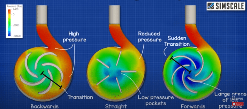
When we compare the results side by side with regards to pressure- The backwards curved design has this nice transition from the centre and out to the edges where the pressure is the greatest so the velocity is turning into static pressure, that’s what we need for the pump to work. The straight blade doesn’t have such a smooth transition, there are pockets of low pressure developing at the centre which is going to impact the blades performance. The forwards curved impeller has the most dramatic results with large areas of low pressure at the centre and sudden changes towards the tips. So, from this we can see that the backwards curved impeller should be the most efficient at transforming velocity into pressure.
If we take a deeper look at the backwards curved impeller, we can see that this design is not perfect and needs some fine tuning. There are regions around both tips of each blade that can be improved to reduce losses.
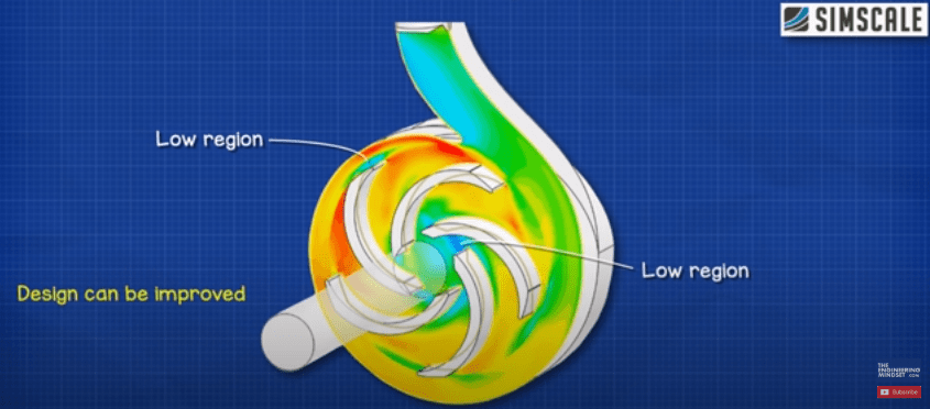
Then if we change the view, we can see there are regions of concentrated pressure between the blades. This is leading to re circulation within the pump. We could use a shroud to reduce this and improve the performance and we can again run that in the simulation to quantify its impact.
To really engineer this design, we would want to run multiple simulations with different blade thicknesses, different blade angles, different diameter impellers and also numbers of blades to find the optimal design. But, this will do for now as it’s a simple project.
Construction
To build the pump, Iwe took some sheets of wood measuring 145mm wide, 170mm high and 12mm thick.
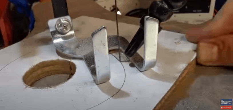
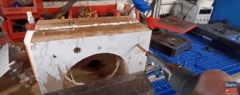
We printed out our volute drawing and then used a trimmer to cut the paper to size and glued this to the wood to use as a template. To save time we screwed two sheets together and then used a scroll saw to carefully cut the centre out from the template. With the centre removed we can see how the pump volute is shaped.

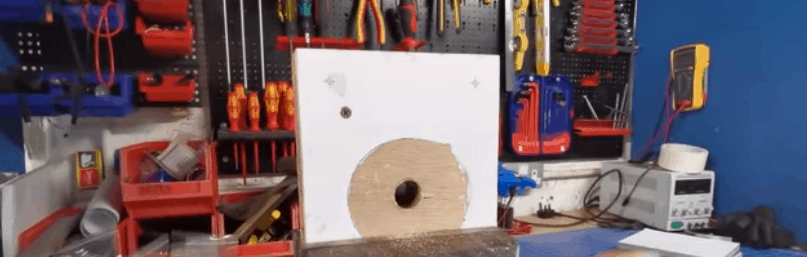
We then glued the template for the back plate to another sheet of wood and used a hole saw to remove some of the internal segment. That allows us to insert the blade of the saw and cut out the centre.
With the main pats of the pump casing made, we then used some strong wood glue to form a seal between each of the sheets and left these to set. Once that was ready we then screwed all three sheets together and used a file and sand paper to ensure a smooth internal surface.

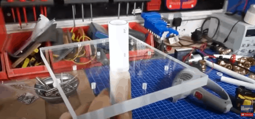
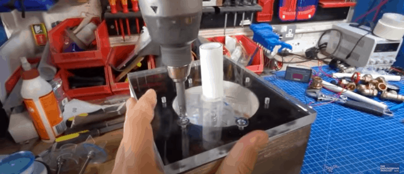
For the front cover we again cut out the paper template and glued this to a sheet of clear acrylic. This will be bolted to the pump casing so we drilled a number of holes using a drill bit which was ever so slightly larger than the diameter of the bolts. We then used a 22mm hole saw to create a hole in the material for the pvc inlet pipe. To try ensure a tight fit we took some wood and filed it down until it fitted inside the pvc pipe. We then heated the pipe with a heat gun until it was mailable and pushed the front cover over this so it would form a seal. This was then covered in hot glue on the inside and outside.
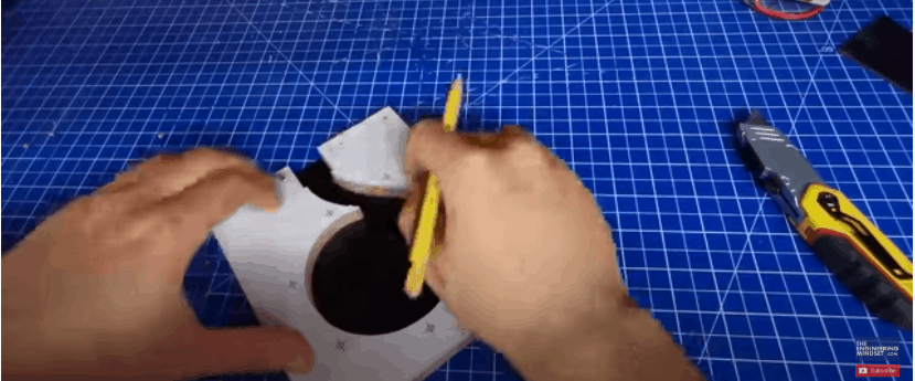
Between the front case and the pump volute we need a rubber seal, for that we’re using a 2mm thick sheet of rubber which we traced the volute outline onto and then cut this out so we could see inside, whilst ensuring a seal around the edge.
For the impeller, we took a 70mm diameter acrylic disc, and found the centre using the centre gauge on the combination set. We then drilled through the disc using a drill bit which is the same diameter as the threaded shaft.
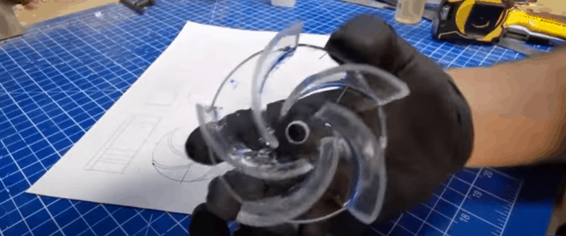
To form the blades, we took some 50mm acrylic tube, and then tightly wrapped, and taped, some white paper around it, making sure that the edges are aligned. The blades are 20mm in height, so we measured this on the tube and used the edge of the paper to draw a line around the circumference. We then cut along the line to remove the section we needed and then placed this segment onto the impeller designs to mark the start and end points. These segments are just cut free from the tube to form the blade.


With all the blades now cut, we took some solvent and applied this to the base of each blade before moving the blade into the required position. The solvent basically melts the materials so they fuse together and form a very strong joint.
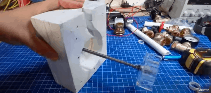
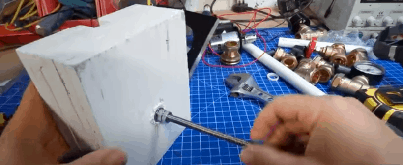
For the bearing housing we again cut out the cad template and glued this to a piece of wood. Once that was set, we attached it to two more pieces of wood and used a hole saw to cut the hole which the bearings will sit in. We then glued the wood together and also joined them with screws.
Once the glue was dry we used a file to remove the excess glue and widen the hole so that the bearings would fit tightly. We then placed the two bearings and a spacer onto the threaded shaft and forced them into position.
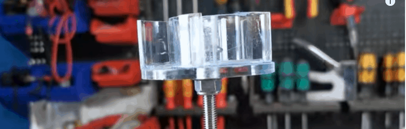
For the shaft we used some stainless steal threaded rods as well as some flanged locking nuts to hold the impeller in place. With the blade temporarily installed we can see it rotates well and there’s a small gap between the blade and the bearing house wall.

The volute casing and the bearing house were glued together to form a seal between the materials and then held together with some extra-long screws. The wood was covered with a white primer and a few layers of a waterproof coating.
To assemble the pump we placed the shaft and impeller into the casing and gave it a quick spin to test it out. We then used a flanged nut and a normal nut on the back to lock them into position. This prevents the impeller from moving back and forth but also allows us to remove it later on.
To attached the cover to the pump casing we used some self-tapping screws, along with a metal and rubber washer. These washers are used to reduce the stress on the acrylic sheet so it doesn’t crack. That’s also why we used a drill bit that was slightly larger than the screw diameter.
For the outlet we simply inserted the 22mm pipe and added a piece of rubber to create a tight joint and then covered these in hot glue to hold them in place. We then fitted a pressure gauge to the inlet and outlet of the pump to take some measurements.
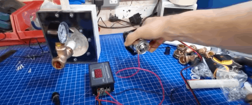
The pump is driven by a 775 DC motor which is controller via a PWM Speed controller. The other two leads then connect into the bench power supply. A simple dial controls the speed of the motor. These parts were then mounted at the back of the motor and joined to the shaft using a coupling.
By the way we have covered how dc motors work – Watch HERE as well as pulse width modulation Watch HERE.
Testing The Pump
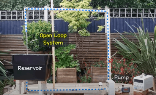
To test the pump we made a simple open loop setup. We have a water tank, and a pvc pipe which runs through a bend, through a ball valve and then into the inlet of the pump. The pump is being driven by the DC motor and speed controller, that is powered by the bench power supply. The outlet of the pump then rises up, through some bends and come back around into the supply tank. We then used a water cup to measure the flow rate.
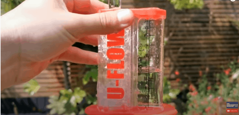
Now as we can see the pump is working quite well. We managed about 16 litres per minute at maximum flow, but the tools and methods we used to test the pump was not accurate enough to compare them with our simulations.
Firstly, the gauges did not read any pressure which makes assessing the pumps performance nearly impossible, so it will instead have to be done through manual calculation and large assumptions. There were some small leaks from the pump, most of these could have been stopped with some waterproof grease but unfortunately, we didn’t have any at the time. The water cup is not exactly a precision instrument but it’s all we have so will have to do. The big problem we faced was cavitation.
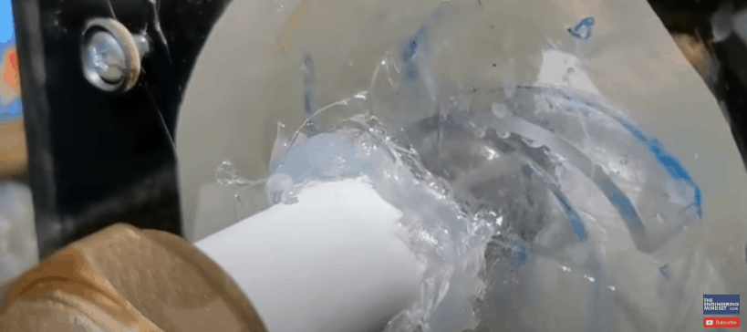
As you can see here, there is air inside the impeller and the rate of cavitation is increasing with speed. This air is being sucked in from small gaps around the inlet pipe because of the low-pressure region created at the eye of the impeller. We also think having the return water fall into the tank, is causing small bubbles in the supply. Now, this is a working prototype so problems like these are expected and now that we know of the issues, we can rectify these in a future model.
How Did the Pump and Impellers Perform?
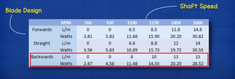
So, how did the pump and impellers perform. In all designs, we can see that no flow developed in the system until the shaft reached around 1000 rpm. Comparing the results of the three different impellers we can see that the backwards curved impeller was the most efficient. That’s because for every Watt of electricity consumed it was able to convert this into more useful mechanical work which results in a higher flow rate compared to the other designs.
The least efficient design was the forwards curved impeller and this was closely followed by the flat blade impeller.

To assess the efficiency of the pump we tried to account for the losses of the electrical motor. From the manufacturers data it shows that the minimum efficiency is around 40% and the maximum is around 72% however both of these figures are calculated during no load conditions and obviously our motor is under load. But we will use these figures just to get a vague estimate.
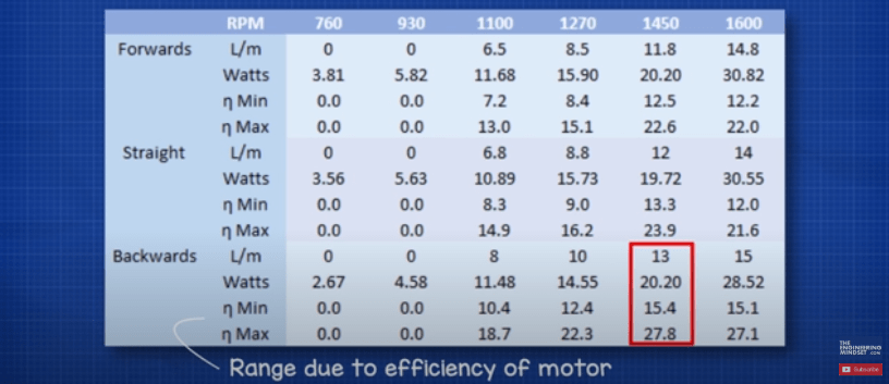
Taking this into account we see that the backwards curve impeller had a peak efficiency range of between 15.4 and 27.8 percent. The straight blades were between 13.3 and 23.9 percent and the forwards curve blades between 12.5 and 22.57 percent. These are just ball park figures though because there any many inaccuracies in the data and measurements and as we know, if you input bad data you get bad results

")
")


")

")