

Learn why electronic component cooling is critical to the design of electronic circuit boards. We’ll look at the different options available as well as how to simulate and virtually test the performance of cooling systems, using computational fluid dynamics.
SimScale provides instant access to computational fluid dynamics (CFD) as well as finite element analysis (FEA) to over 200,000 users. SimScale has moved high-fidelity physics simulation technology from a complex and cost-prohibitive desktop application to a user-friendly cloud application accessible via a subscription-based pricing model.
Try for SimScale free:➡️ https://bit.ly/2N9Ugmt
Scroll to the bottom to watch the YouTube video.
All of our electrical devices are built by combining different electronic components together. Each component has a specific function. Take this very simple lighting circuit for example. The battery provides the electrical energy, the LED produces light from the energy supplied by the battery and the resistor protects the LED by reducing the current in the circuit. If we remove the resistor the LED will instantly burn out.
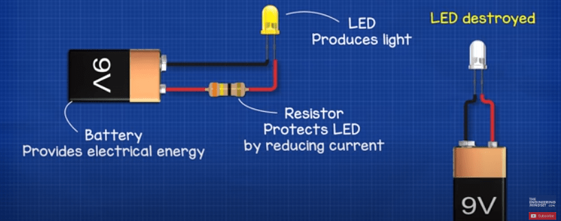
Why Does the LED Burn Out?
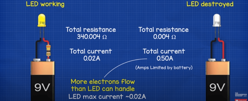
Because the resistance of the circuit reduced, meaning it becomes much easier for more electrons to flow from the battery and through the LED component which you can only see under a microscope.
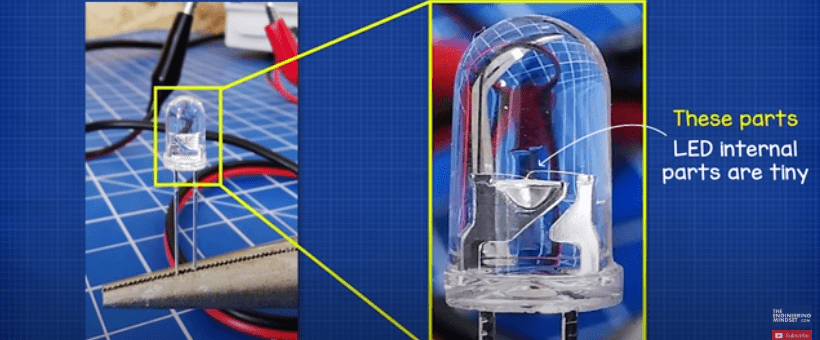
They can only cope with a certain amount of electrons flowing through them, otherwise they will burn out. On the other hand an electrical cable is much thicker so it can handle far more current flowing through it. That’s why we have different sized cables, to handle different amounts of electrical current.
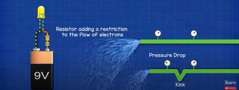
Coming back to the resistor, this is essentially adding a restriction to the flow of electrons. It’s like having a kink in a water pipe, the kink restricts how much water can flow through the pipe and the water is now colliding with the pipe wall so it wastes energy and will result in a pressure drop. As we know, pressure is like voltage and the resistor is like the kink in the pipe. So, when we add a resistor to the circuit, we restrict the current or the amount of electrons flowing and we get a voltage drop.
Why Do We Get a Voltage Drop?
Well if we look at a normal copper wire, this is made from millions and millions of copper atoms. Copper is a conductor which means the copper atoms have an eletron which is free to move around between other atoms. They do move naturally to other atoms, but randomly in any and all directions. If we apply a voltage difference across the wire, the voltage difference or pressure of the battery will force electrons to flow through it.

But with a resistor, the material is less conductive and creates a harder path for the electrons to flow through. The electrons are going to collide and as they collide their energy is converted into heat. So the energy of the battery is really being wasted and turned into heat. Because the energy of the battery is being removed by the resistor, we get a voltage drop.
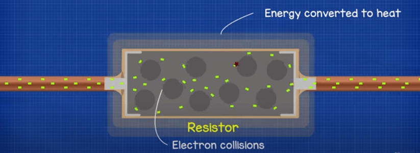
That’s why when we look at the resistor through a thermal imaging camera, we can see it is generating heat.
Some components such as mosfets and igbt’s will produce a lot of heat.
Take this cheap bench power supply for example.

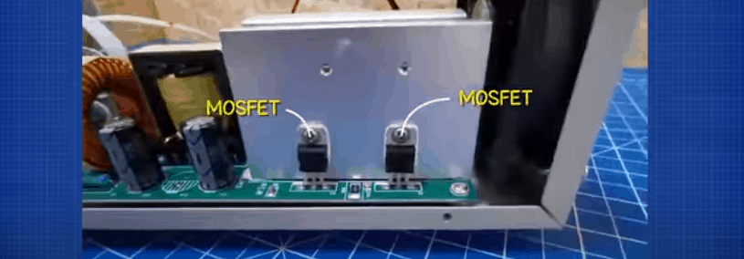
It has 4 mosfets inside, 2 here:
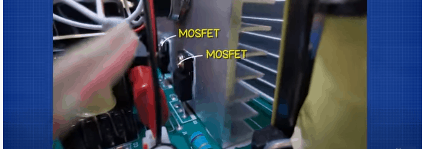
And 2 here:
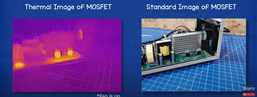
If we remove the heat sink, we’ll look at that part a little later, and then power a small DC circuit with about 1.2A we can see with the thermal imaging camera that these components very quickly reach 45 degree Celsius and that’s with the fan on. We cut the power here because we don’t want to damage them.
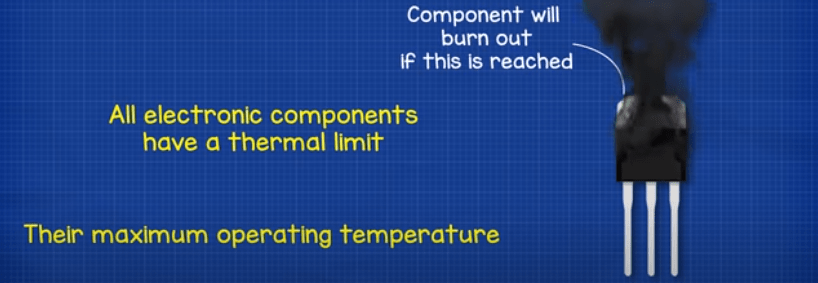
All electronic components have a thermal limit or a maximum operating temperature. When they reach or exceed this certain temperature, they will breakdown and potentially destroy the circuit board.
For some components like a fuse, this is desirable because the material breaks and this instantly cuts the power to the circuit, which does help to prevent component damage but it also completely stops the circuit board from working until the fuse is replaced.

With components like an IGBT, the build-up of heat isn’t a good thing because as they increase in temperature, they become unreliable and the current passing through them increases. This additional current creates more heat which in turn allows more current to flow, so the component reaches thermal runaway and will eventually just destroy itself. So, to increase the life span of the components and circuit board, as well as keep the component operating in a stable, reliable condition, we need a way to remove the thermal energy it generates.
How to Remove Thermal Energy From Electronic Components?
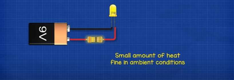
Some components such as this simple resistor LED circuit will operate fine in ambient conditions, they do not produce much heat and any heat they do produce will dissipate into the ambient air.
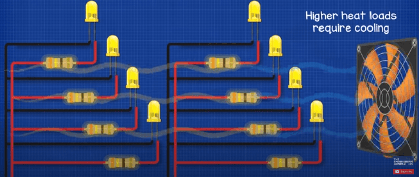
When the heat starts to increase, we can use a simple fan to blow air across the component. The moving air will pick up and carry more heat away. This is the method used on PC’s and that’s why there is a fan inside to literally remove heat from the internal components.
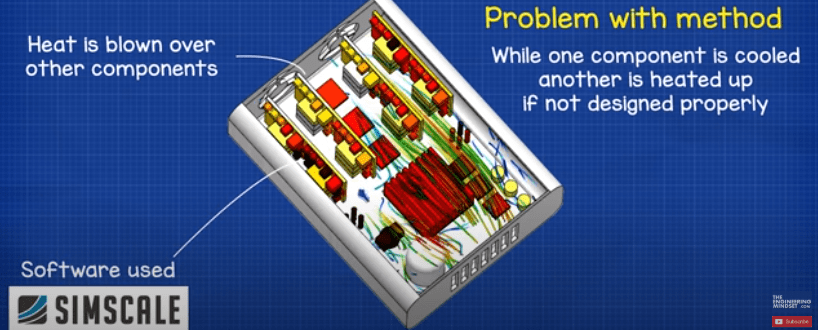
This simulation was run in a web browser, using SimScale, which we will look at in detail a little later in this article.
But there is a problem with this method, we’re blowing the heat off one component and this hot air then passes across other components, so we are cooling down one component but if we’re not careful with the design we will heat up others.
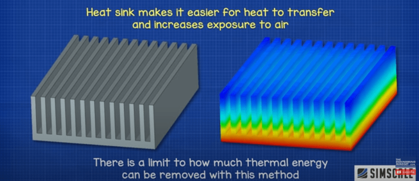
We usually need a more effective way to get the heat out of the component and a popular method is to use a heat sink to provide passive cooling. This heat sink is usually an aluminium or “Aluminum” (US) block which has lots of fins. The fins help to increase the surface area of the component to allow exposure to more ambient air. The heat sink is made from metal because it conducts heat well, much better than air. So, by making it easier for more heat to escape and increasing the exposure to air, we effectively cool down the component. There’s a limit to how much we can remove with this method though.
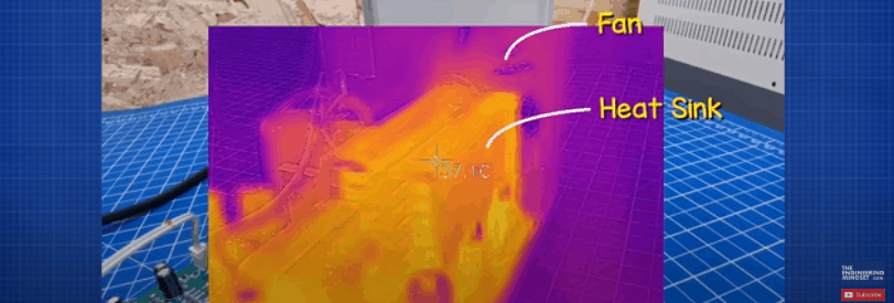
The next stage is to attach the component to a heat sink and then use a fan to blow ambient air over the component and heat sink, to increase the heat removal. That’s exactly the method used in this DC bench power supply. The fan and heat sink are combined to remove the excess heat.

You can see the heat is dissipating out through the heat sink and when we cut the power but leave the fan running, it drops in temperature very quickly.
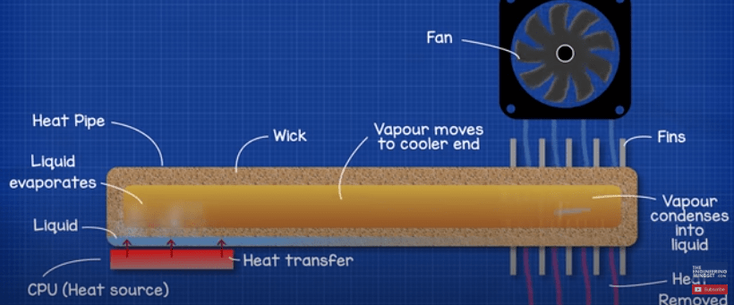
Another method that’s most commonly used in laptops is to use a heat pipe. That’s the strange orange bar that you’ll see inside your laptop running between the processor and the fan.

Inside this is a small amount of liquid and a wick. The heat of the processor is absorbed into the pipe and this heat causes the liquid inside to boil and evaporate, the vapour moves towards the opposite end which is cooler because the fan is blowing air across the surface and this removes the heat from the heat pipe. This removal of heat causes the vapour to condense back into a liquid and this liquid flows back along the wick to pickup more heat, and so the cycle repeats.
These again have a performance limit and to increase the heat removal we have to start using these huge units, which take up a lot of space and again blow the heat over other components.
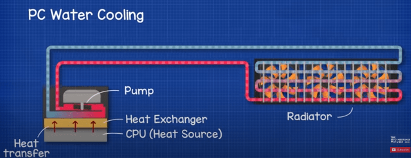
The next stage for maximum cooling is to use water, or liquid cooling. You may have seen many high spec gaming computers now start to use a water-cooling system to remove heat from their CPU and GPU.
We basically have a small pump which cycles water between the heat exchanger of the CPU, known as the water block, and the radiator, which is a heat exchanger with some fans. Again the fans will blow air across the heat exchanger and remove the unwanted heat from the water, so the water picks up the unwanted heat from the chip, carries this to the radiator and then flows through the heat exchanger of the radiator. As it flows through, the fans blow air across the outside which removes the unwanted heat. The water therefore leaves cooler and returns to the chip to pick up more heat.
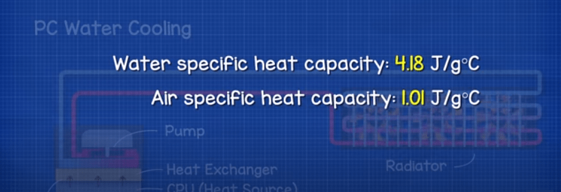
The reason this method is so efficient is because water has a substantially higher heat capacity than air. So, it can pick up more heat. Rather than pushing air across the fins and blowing the heat across other components, the water-cooled system is collecting the heat and moving this away, then rejecting it completely from the system.
This method is increasingly used in power electronics especially in high power applications where we often find these banks of IGBT’s. These generate vast amounts of heat and need to operate reliably for long periods of time.
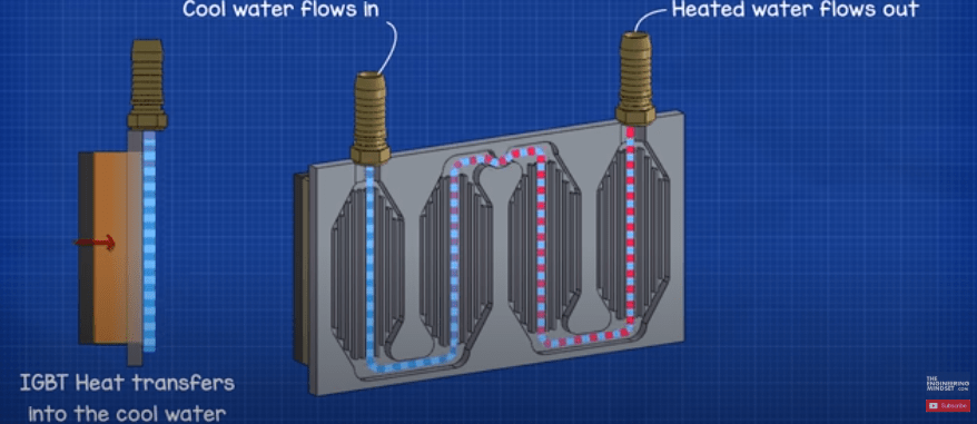
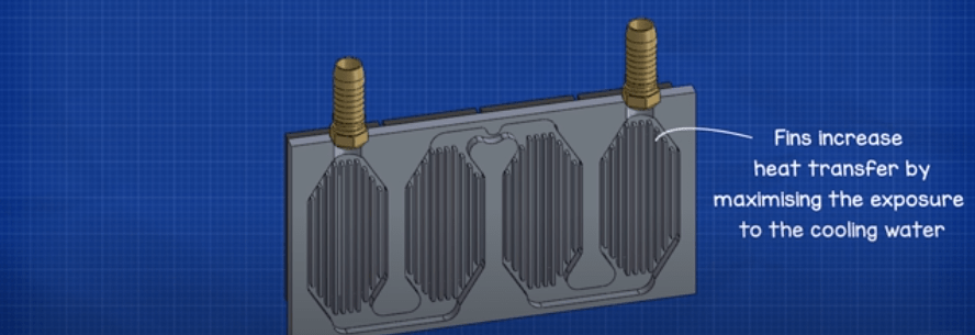
As we saw with the bench power supply the IGBT’s were spaced out and take up a lot of room. So instead, what we can do is mount these to a thermal block which is basically a heat sink or heat exchanger that water flows through instead of air. As the IGBT’s generate heat, this will pass through the block and into the water. Between the IGBT’s and the thermal block we have a thick layer of thermal paste which just helps to increase the transfer of heat. Inside the block we have these fins to help increase the surface area of the heat exchanger and maximise the exposure to the cooling water to remove the heat.
We want to ensure that these particular IGBT’s do not exceed 90 degrees Celsius (194 F).
To do that we’re going to simulate the performance by utilising the SimScale CAE platform. SimScale provides instant access to online computational fluid dynamics as well as finite element analysis via a user friendly cloud based application available through a simple subscription model. No installation is required. You can try the software for free and edit public projects at simscale.com via their community account, or you can create private projects with enhanced features via their professional, team or enterprise accounts. If you want to try this software out yourself CLICK HERE.
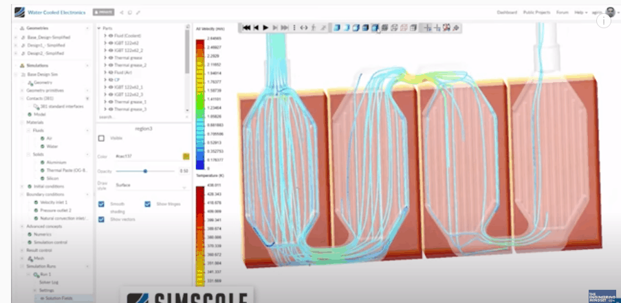
So, after we design our CAD model, we can import this into SimScale for analysis. We input our variables such as the materials being used, the thermal power emitted by the IGBT’s, the flow rate and outlet pressure of the water etc.
This provides our base analysis which shows the IGBT’s are going to operate at around 165°C (329.F) which is far too high and will result in the destruction of the components and also our circuit board.
The first change we will make is to the materials, so we will use aluminium for the heat exchanger which has a higher thermal conductivity. This means heat can pass through it much easier. We will also use thinner plates so the IGBT’s are closer to the heat transfer area. Making it easier for the heat to reach to cooling liquid.
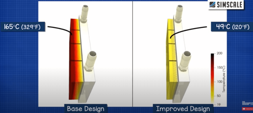
As you can see these simple changes have made a dramatic effect. Our IGBT’s are now down to around 49C, which is perfect as it’s below our thermal limit of 90C and provides a good buffer before we would hit that limit. So now we can improve the efficiency of the design.
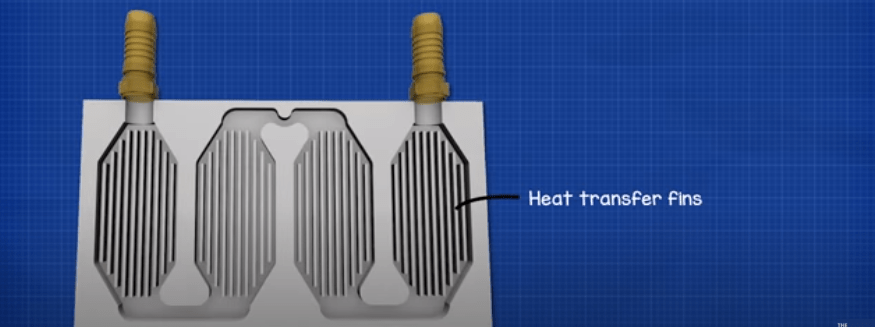
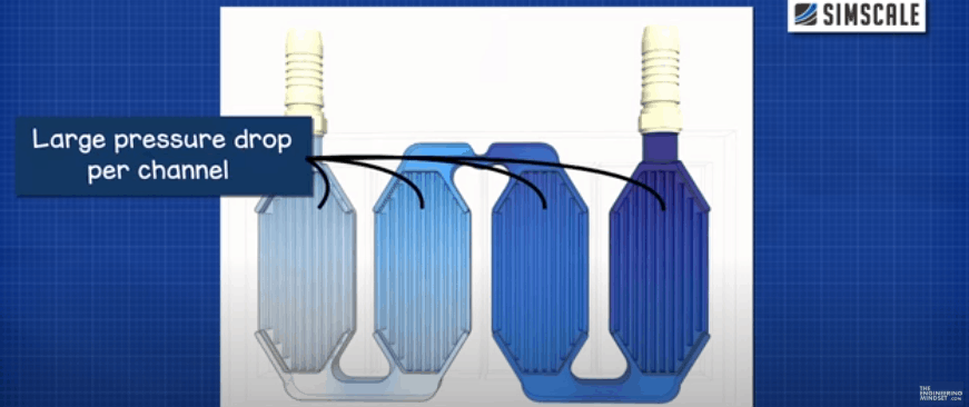
The original design has these fins running through the heat exchanger which help to expose the water to the heat of the IGBT’s. But we can see that this design causes a high pressure drop in each channel. The pressure drop of each channel adds with the pressure drop of the next channel, over all the pressure drop across the unit is large as well as being inconsistent through the unit.
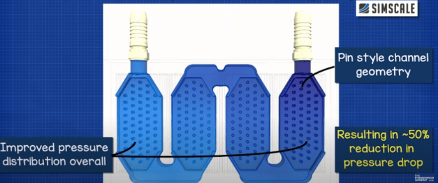
So instead we’re going to use pin style design channels, and when we run the simulation of this we see a much more even pressure distribution across each of the channels and a lower pressure differential across the entire unit leading to improved cooling performance of the heat sink.
So just by simulating the cooling system in SimScale and making simple design alterations, we can very quickly make drastic improvements to the performance of our cooling system and ensure our expensive and critical electronic circuit boards are operating within their limits, to maximise reliability and life span as well as operating efficiently.


")

")


")

")
[…] So it’s important to keep them cool and prevent them from getting too hot and damaging the electronic components inside. Solar inverter overheating is best prevented by ensuring a well-ventilated area and keeping […]