

Learn the basic principles of a DC series circuit from voltage, current, resistance and power consumption to using a multimeter. There’s also a problem for you to solve, with answers, at the end.
Scroll to the bottom to watch the YouTube tutorial.
Remember Electricity is dangerous and can be fatal, you should be qualified and competent to carry out any electrical work.
What Is a DC Series Circuit?
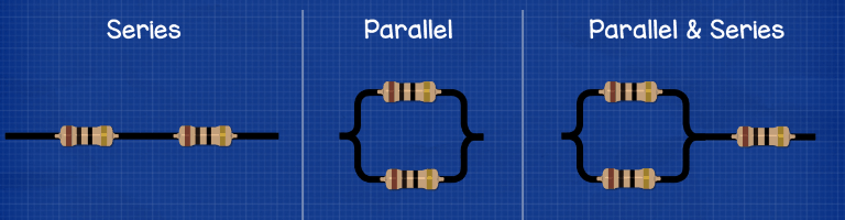
When we connect components in an electrical circuit, we can connect them either in series or parallel, or we can combine these to make a series parallel circuit. This article details the series type which is the most basic, we’ll cover the other types in other articles which you can read HERE.
If we place two components in a line, end to end, or with some wire in between, then these are connected in series. The electrons only have one path they can take so they will all flow through each of the components.
Just to note, in these animations we use electron flow which is from negative to positive. You might be used to seeing conventional current which is from positive to negative. Electron flow is what’s actually occurring, conventional was the original theory but it’s still taught because it’s easy to understand. Just be aware of the two and which one we’re using.
Resistance In Series Circuits
Each component will have a certain resistance, the resistance opposes the voltage being applied. We measure resistance in the unit of Ohms with the Ohm symbol Ω.
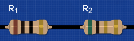
In series circuits; we find the total resistance of the circuit by simply adding all the resistances together. We label each resistor with a capital R and number them R1, R2, R3 etc.
The total resistance is shown with a capital R and a subscript T which represents the resistance total or total resistance.
To calculate the total resistance of a series circuit is super easy, we simply add together the resistance value of each resistor.
Lets say we have a circuit with a single resistor, that’s our R1, and this has a value of 10 Ohm’s. What Is Our Total Resistance? Well that’s easy, the total resistance is 10 ohms.
If we then add a second resistor R2, with 5 Ohm’s of resistance into the circuit, the total resistance is now 15 ohms, 10 Ω + 5 Ω.
If we added another 5 Ω resistor then the total resistance is now 20 ohms.
In reality the wires too will add some resistance but this is very small, you might need to account for this depending on how accurate your design needs to be.
Current In Series
Current is the flow of electrons. It’s like the water that flows through a pipe. The higher the current the more electrons are flowing. We measure current in the unit of Amperes but engineers tend to shorten this to just Amps. This is represented with the capital letter A.
We’ve covered current in detail in our previous article, do check that out HERE.
We measure current by placing an ammeter into the circuit for the electrons to flow through. This is like a water meter in the sense that water must pass through it for us to measure it. We can connect a multimeter into the circuit to also read the current.
The multimeter must be place into the circuit to take a reading, the current will flow through this. The meter will add some resistance to the circuit, but it’s such a small amount we can usually ignore this.
If you don’t have a multimeter yet then we highly recommend you get one, they are essential for trouble shooting and building your understanding. You can buy them using the link below.


We can calculate the total current for the circuit by dividing the voltage by the resistance.
If we connect a 10 ohm resistor to a 9V battery, 9V ÷ 10 ohm gives us 0.9A.
If we added another 5 ohm resistor to the circuit, that gives us 15 ohms resistance, so 9V ÷ 15 ohm =0.6A.
Then, if we added another 5 ohm resistor, that gives us 20 ohms resistance so
9V ÷ 20 Ohms = 0.45A.
We can see that as we add more resistance to the circuit, the current reduces so less electrons are flowing and that means we can do less work. We can visualise that by connecting an LED with a resistor in a circuit. The higher the resistance; the dimmer the LED will be.
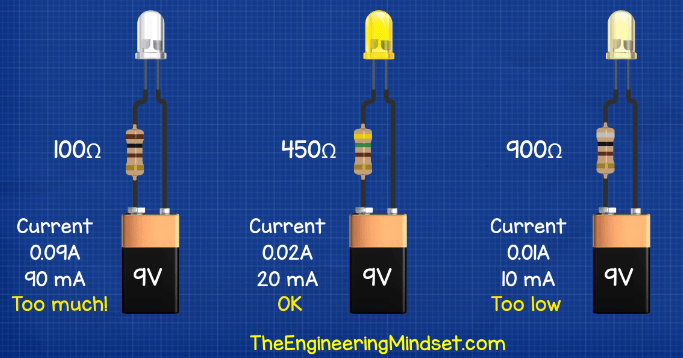
We can also use resistors to protect components in the circuit. If we use a 100Ω ohm resistor with a 9V battery, the current will be around 0.09A or 90mA and that will blow the LED. If we use a 450ohm resistor; the current will be around 0.02A or 20mA so the LED should be ok. If we use a 900ohm resistor, the current will be 0.01A or 10mA and the LED will be very dim.
In a series circuit; the current is the same throughout the entire circuit. That’s important to remember that. As detailed below; if we placed the meter in either places we get the same reading. That’s because there is only one path for the electrons to flow along and they all move together in the same direction, so
the current must be the same. It doesn’t matter where we measure or where we place the resistor, even if we swap the order of the resistors, the current will be the same anywhere in a series circuit.
Voltage in series
Remember voltage is the pushing force of electrons, it’s like pressure in a pipe. The higher the pressure; the more water can flow, the higher the voltage; the more electrons can flow. We can see that by varying the voltage to a lamp as illustrated below, the lamp increases in brightness as the voltage increases.

If we place a 9V battery into the circuit, we apply 9V to the circuit. We can increase this by wiring batteries in series.
So If we place two 9 batteries in a circuit in series then we get 18V, three 9V batteries will give us 27V.
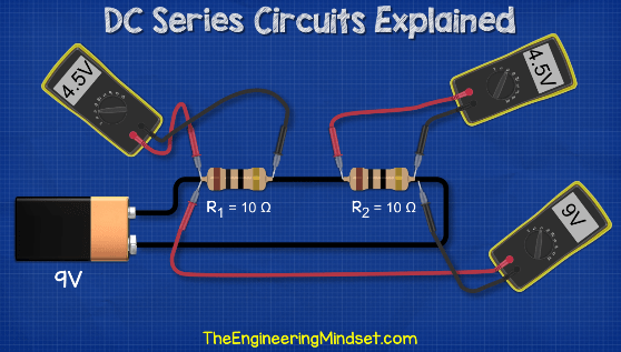
Let’s take a 9v battery and add in an R1 resistor of 10ohm to the circuit. If we use a multimeter to measure across the resistor, we get a voltage reading of 9V. If we added another 10 Ohm resistor, we get a reading of 9V across the two resistors but we get a reading of 4.5V if we measure across either of the resistors individually. So the resistors are dividing the voltage.
If we replaced the R2 resistor with a 5ohm resistor, the total voltage would again be 9V and that’s what we see if we measure across the two resistors. But if we measure across the 10ohm resistor, we see a voltage of 6V and if we measure across the 5 ohm resistor we see 3V.
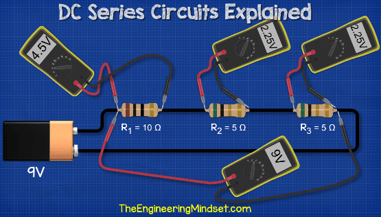
If we added another resistor R3 with 5 ohm into the circuit we again get a total voltage drop of 9V across the 3 resistors. Across the R1 10 ohm resistor we read 4.5V, across the R2 5 ohm resistor we read 2.25V and across the last R3 5 ohm resistor we see again 2.25V.
We can combine these readings to find the voltage at different parts of the circuit. For example if we measure from the battery and across R1 we see 4.5V. If we measure from the battery across R1 and R2 we get 6.75V because 4.5V + 2.25V.
So unlike current where it’s the same throughout the circuit, the voltage will be different throughout a series circuit.
This shows us that the voltage is reduced by each resistor, so the resistor creates a voltage drop. That’s the purpose of the resistor, to reduce the voltage or the pressure. What’s happening is the resistor creates a more difficult path for the electrons to flow through and as they flow through they will collide with other electrons. This collision will convert the energy into heat. The same amount of
electrons will enter and exit the resistor, they will just have less energy or pressure so there is a voltage drop.
Calculating Voltage Drop
We can calculate the voltage drop across each resistor individually by multiplying the total current in the circuit by the resistance of the component. Remember in series circuits the current is the same anywhere in the circuit. The total voltage drop will be the total of all the individual voltage drops combined.
The first circuit, there was a 10 ohm resistor by itself. The circuit had a current of 0.9A so 0.9A x 10 Ohms = 9V. The voltage drop across the resistor is therefore 9V, the same as the voltage source.
The second circuit had a 10 Ohm and a 5 Ohm resistor together and this circuit had a current of 0.6A, so the first resistor voltage drop is 0.6A x 10 Ohm = 6V, the second resistor was 5 Ohms and the current was the same, so 0.6A x 5 Ohm = 3V. The total voltage drop is 6V + 3V = 9V.
The third circuit has a 10 Ohm and two 5 ohms resistors, the circuit had a current of 0.45A so R1 is 0.45A x 10ohm = 4.5V, R2 and R3 will be 0.45A x 5ohm = 2.25V.
The total voltage drop is therefore 9V (4.5V + 2.25V + 2.25V).
Power Consumption
How do we measure power consumption of the circuit? We can use the following equations:
Either
Power (watts) = Voltage 2 / Resistance
Or
Power (watts) = Voltage x Current.
You might be wondering how can a resistor consume power? Well as the resistor is creating a voltage drop, the electrons are losing some energy. Where is this energy going? The electrical energy is being converted into heat which when looking at some resistors under a thermal imaging camera, we can see the heat being generated.
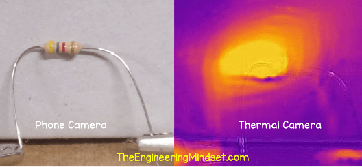
So the power consumption is actually the heat being dissipated from the circuit.
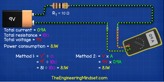
In this circuit the resistance is 10 Ohm, the battery is providing 9V the current is 0.9A and the circuit consumes 8.1W. How do we calculate that? Using method 1, 9V squared or 9 multiplied by 9 is 81, ÷ by 10 Ohms is 8.1W. Alternatively 9V x 0.9A = 8.1W
In the next circuit with the 10 Ohm and the 5 Ohm resistor, the total resistance was 15 Ohms and the current was 0.6A, so
9V squared is 81, divided by 15 Ohms is 5.4W
or 9V x 0.6A = 5.4W.
In the circuit with the 10 Ohm and two 5 Ohm resistors, the total circuit resistance was 20 Ohms and the current was 0.45A, so
9V squared is 81, divided by 20 Ohm is 4.05W
or 9V x 0.45A = 4.05W
Can you solve this problem?
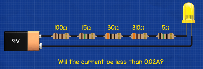
Problem: the LED is connected to a 9V battery and the current in the circuit must be limited to a maximum of 0.02A or 20mA else the LED will burn out. If we connected to these resistors, what will the approximate circuit current be and will the LED burn out?
Answer: First we need to calculate the total resistance for the circuit. We do that by adding together all the resistor values.
100+15+30+310+5 = 460 Ohms resistance
Now we calculate the current by diving the circuit voltage by the resistance.
9V ÷ 460 Ohm = 0.0195A
That’s less than our maximum of 0.02A so it should be ok.


")


")


")
In all of your LED examples you do not take into consideration the voltage drop across the LED. I am new to electronics and my first ever circuit design involved an LED with a forward voltage of 3.2V (a 10mm white LED). The datasheet tells me that the forward voltage is 3V and that the LED is happiest at 30mA. I’m powering the circuit with a 9V battery.
So… the resistor required is:
R = 9/0.03 = 300Ohm
When I check my calculations (I appreciate there’s not many and they’re not very complex) I find some people recommending that I take the forward voltage of the LED into consideration:
R = (9V (the battery) – 3V (voltage drop from the LED)) / 0.03A (the current required) = 200 Ohm
Which is correct?
PS: since I wanted a night light effect I went with 330 Ohm resistors. The LEDs light dimly, but acceptable for this project. I also built one with two 330 Ohm resistors in parallel (i.e. 165 Ohm) which should have slightly overdriven the LED, however, my bench power supply said the circuit was still only consuming 23mA (confusing since my calculations expected in excess of 30mA). I later decided to check the accuracy of the bench supply… it was well out and actually my modified circuit was consuming 32mA (according to my Fluke meter) – overdriving the LED a little. Lesson learned – get a more accurate bench power supply 🙁
I don’t see any comments concerning your electrical problem and the possible inaccurate answer. A 9V battery connected in series to a LED light with 20 mA capacity with a total of 460 Ohms resistance. I = (9^2)÷460= .176 A or 176 mA. It seems the 9V was not squared.
Noticed this also!
You’re mixing up the formulas.
Current I = V / R
Power P = V^2 / R
Use the calculator or Ohm’s triangle
lol
Sorry about the repost. This was all for the sake of learning. I don’t see any comments concerning your electrical problem and the possible inaccurate answer. A 9V battery connected in series to a LED light with 20 mA capacity with a total of 460 Ohms resistance. I = (9^2)÷460= .176 A or 176 mA. It seems the 9V was not squared.
Same thing for me
Hi, thank you for the interactive lesson. So I wonder the application for the voltage divider. Let’s take example like this:
I want to power on a LED with voltage operation rated between 5V ~ 4V. In my possession, I have:
– 9V battery
– R1 = 10 ohm ; R2 = 5 ohm ; R3 = 5 ohm
Based on the lesson, if I want to safely operate the LED, I can connect it on the circuit between R1 & R2.
Is that how it works ?
That’s incorrect – what you just did there is find for Power (V x I or [V^2]÷R) not Current. According to Ohm Triangle finding for I = V÷R .
My own answer correct me if i wrong:
9V÷460ohms = 0.019
R1 =1.9v
R2=0.28v
R3=2.7v
R4=5.89v
R5=0.09v
1.9+0.28+2.7+5.89+0.09=10.3v
R1 = 1,9 V (100*0,019)
R2 = 0,285 V (15*0,019)
R3 = 0,57 V (30*0,019)
R4 = 5,89 V (310*0,019)
R5 = 0,095 V (5*0,019)
1,9+0,285+0,57+5,89+0,095=8,74 V (~9 V)
(The error comes because we used 0,019 instead of 0,195652174… or (9/460))
Not sure how you got those answers. It’s best if you show the formula used. I’m confused how you got R3 so you might want to check that.
9V / 460ohms = 0.0196A (Rounded up from 0.01956521739130434782608695652174)
R1= 100ohms *.0196A = 1.96V
R2= 15ohms * .0196A = 0.294V
R3= 30ohms * .0196A = 0.588V
R4= 310ohms * .0196A = 6.076V
R5= 5ohms * .0196A = 0.098V
1.96+0.294+0.588+6.076+0.098=9.016V
Hope this helps.
Your adding is incorrect.
1.9+0.28=2.18
2.18+2.7=4.88
4.88+5.89=10.77
10.77+0.09=10.86V
R1 = 1,9 V (100*0,019)
R2 = 0,285 V (15*0,019)
R3 = 0,57 V (30*0,019)
R4 = 5,89 V (310*0,019)
R5 = 0,095 V (5*0,019)
1,9+0,285+0,57+5,89+0,095=8,74 V (~9 V)
(The error comes because we used 0,019 instead of 0,195652174)
What is the answer in current?
In the video, you’re saying the formula is W = V^2 / R
But in the answer, you’re doing W = V / R
9^2 = 81
81 / 460 = 0.176W
That’s more than our maximum of 0.02A so it is not ok. Right?
Oh, dammit. No, it’s all good. Totally confusing Watts and Amps now. After that previous calculation, I’d need to then go 0.176 / 9 = 0.0195
Cool, thanks!
Can’t we Download the PDF of these notes? If can then how?
0.0195