Learn how to calculate circuits with capacitors in parallel with this tutorial on electronic engineering.
Scroll to the bottom to watch the YouTube tutorial.
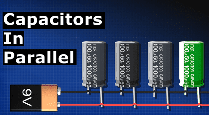
If we place a capacitor in parallel with a lamp, when the battery is removed, the capacitor will begin to power the lamp. It slowly dims as the capacitor discharges. If we use two capacitors, we can power the lamp for longer. Let’s say capacitor one is ten microfarads and capacitor two is 220 microfarads. How do we calculate the total capacitance?
Well, that’s very simple. The answer is 230 microfarads. The capacitors combine in parallel, so 10 + 220 equals 230 microfarads. We can keep adding more such as a 100 microfarad capacitor. And the total is just the sum of all of the capacitors.
By placing them in parallel we are essentially combining these to form a larger capacitor. That’s very useful because if, for example, we needed a large 2000 microfarad capacitor, but we didn’t have one. We could just use more smaller capacitors, such as two 1000 microfarads or 4500 microfarads, etc. It’s also often used for filtering out noise and to provide more current in high demand circuits.
The total charge stored in parallel circuits is just charge equals the total capacitance multiplied by the voltage. So here we have a nine volt battery and two capacitors with a total capacitance of 230 micro Farads as this is parallel, this wire is 9 volts and this wire is 0 volt. So both capacitors are charged to 9 volts. Therefore, 23 microfarads multiplied by 9 volts will give us 0.00207 Coulomb.
And with the three capacitors, we have 330 microfarads. We multiply this by the nine V to get 0.00297 coupons. We can also calculate the charge of each capacitor individually. We just use the same formula for each capacitor.










Love your videos
Wondering about using capacitors to help with voltage drop during motor start?
I use a balanced commercial rotary phase converter to get 220 3ph for a CNC machine.
The CNC motor start and speed control is handled by the servo drives.
When the CNC motor starts (30HP motor) there is a large amp draw (400 amps) and dims lights for .5 sec then operates fine.
During normal operation 50 amps with 70 amp spikes.
I am limited on how much I can adjust the servo (soft start) without effecting many other settings.
I am in the country and have updated the building power supply to 400 amp 220v single phase. Power company says, “its the best they can do for me”
All wiring has been upgraded in the building and according to the power company the problem is on “their side” due to my location on the grid.
Problem is worse when there is high draw on our grid circuit.
So wondering about using capacitors in the main line to help with voltage drop power draw?
What other options should I look into?