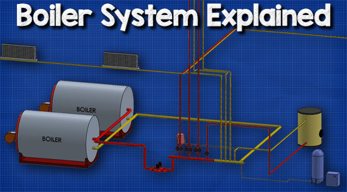
Boiler system explained (LTHW). In this tutorial we are going to be looking at a typical modern heating system in a commercial building. There are many variations of how this can be configured, but this version is fairly typical of the newer construction commercial buildings.
Scroll to the bottom to watch the YouTube tutorial on boil systems
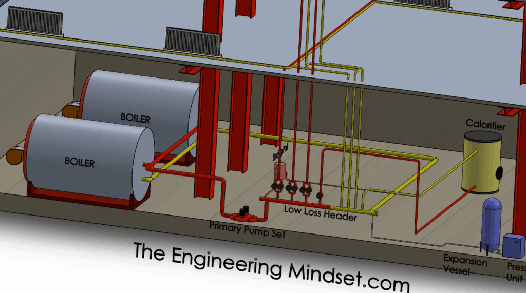
In this system we have two large boilers which are connected in parallel. This means that both boilers can operate at the same time or individually. One of the boilers could be isolated and cut off and opened up for maintenance while the other boiler continues to run and provide heating to the building. This is the most common type of configuration for modern heating systems. The other version would be connected in series, but this is an outdated design which isn’t so practical, at least for commercial offices.
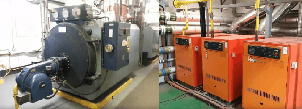
Boilers come in many designs, I’ve given some examples above. They may be a couple of large boilers or multiple smaller units. Better designs will use a mixture of sizes to efficiently suit the demand. Perhaps a large for winter and smaller for summer.
These boilers are the heat source for the heating system. That heat is transferred into the circulating water of the heating system which is then pushed out and around the building.
There are two terms you’ll come across in these sorts of systems, primary and secondary circuits.
The primary circuit will circulate hot water from the boilers and around to the low loss header. The low loss header will provide hot water to the secondary circuits and then return the cooler used hot water back into the other end of the low loss header.
The water of the primary circuit can flow straight through the low loss header and back to the boiler to pickup more heat, or it can flow up through the secondary circuits. The path the water takes will depend on the demand for hot water in the secondary circuits. The water can flow straight through because the boilers require a minimum flow rate to operate otherwise they can damage or destroy their internal parts.
The primary and secondary circuits will each have their own pump sets.

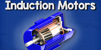
The primary pumps tend to be the larger pumps, typically centrifugal type driven by an induction motor. This depends on the size of the system though, they could also be inline type especially in smaller office blocks.
Detailed explanation of Primary and Secondary sides covered here
The primary pumps will only push water around the primary loop. That hot water leaves the boiler, enters into this pipework, is sucked by the primary pump and then pushed out into the low loss header.
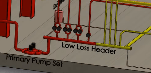
That water can then either exit through the secondary pumps coming off the low loss header and flow into the risers, or some of it will continue through into the other side of the header. In either case, the water will reach the far end of the header and continue flowing around, back to the boiler, but at a lower temperature to pick up more heat and repeat that cycle.
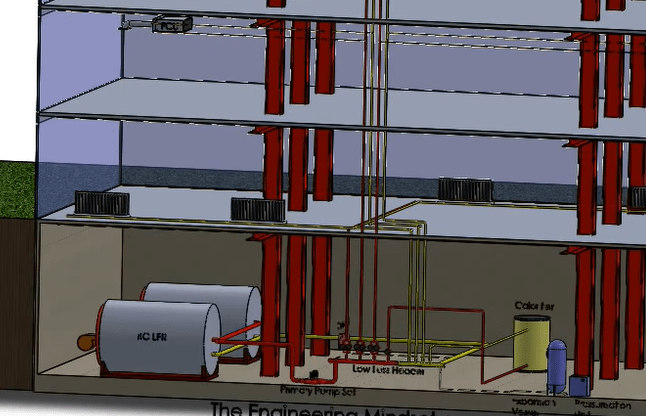
Coming off of the header, from the hot side, are some smaller pumps which are connected to pipes known as risers. The risers rise up the building to provide the heated water to different circuits. For example the East or West wing AHU’s.
In this example, we have four secondary circuits. Secondary circuits 1 – 3 have dual pump, and the 4th one has just a single pump as it’s heating load is small and nearby, perhaps the reception desk area.
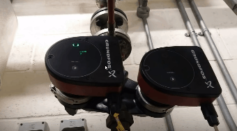
Above you can see an example of some smaller secondary pumps. They could also be large centrifugal pumps, it depends of the size of the heating system. These pumps will force the hot water up to wherever it’s needed, but only for the selected area of the building which the pipework has been connected to.
Dual pump setups will usually work in duty and standby. This means one pump runs at any given time while other acts as a backup should the duty pump fail.
The secondary circuits will provide water to defined area of the building. For example the first circuit might provide hot water to the radiators on the first floor. The second, secondary circuit might provide hot water to the Air handling units and Fan coils on the east side of the building only etc. etc.
Once the hot water has cycled through a heat exchanger and given up some of it’s thermal energy, it will return, via a return riser, where it will flow back to the low loss header and back to the boiler to pickup more heat.
Domestic Hot Water
In this example, we also have a secondary circuit going off and feeding into a calorifier. The calorifier is where the domestic hot water is produced, this is the hot water that comes out of the taps.
Why do we separate the the domestic water from the hot water pumped around the building? There’s a lot of chemicals that go into primary heating system of an LTHW system, low temperature hot water system, and you don’t really want to drink that.
The hot water is fed from the boiler and into a secondary circuit where it will then be forced by a pump into a heat exchanger within the calorifier. It will then transfer its heat into some fresh water which is held inside the tank. That fresh water will inevitably increase in temperature as a result of the heat exchanger. This heated fresh water is then supplied to the kitchens, tea areas and bathroom sinks where it will be used and flow down the drain. It will not return back to the heating system. Meanwhile, the supplied hot water, from the boiler, in the secondary circuit will flow out of the heat exchanger within the calorifier at a lower temperature, because it gave up some of its heat to the fresh water, and it will return back to the low loss header and back to the boiler.
Pressurisation Unit

Above you can see an example of an expansion vessel and a pressurisation unit. The pressure in the system is going to change, for example, if the secondary pump set turns on, then the primary pump set is going to see a pressure decrease, because more water is now flowing out of the header and into the secondary loop.
The same if the water increases or decreases in temperature, it’s going to change in density, and that is also going to affect the pressure as well. Water expands when heater and shrinks when cooled.
The expansion vessel and the pressurisation unit is connected into the main pipework, usually into somewhere around the low loss header. If the pressure gets too high, then obviously the expansion vessel will absorb some of that, and when it gets too low then the pressurisation unit will force that back into the system to equalise it.
System Dosing
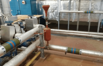
Above you can see an example of a dosing pot. That is usually installed with some thin pipework connected across the low loss header. This will then use the pressure difference to flush hot water through it. The dosing pot just allows chemical inhibitors to be poured into the system which just keeps it clean and bacteria-free.










Are there any books you would recommend to buy showing all of the plant expected in a building?
Is it possible that a low loss header could require two fill points or what would cause a system to only fill on one side as I have experienced there is NRVS along with pumps on the flow circuits off the header and that’s where a pressurisation unit with expansion vessels was fitted. But I could only get the system to fill through the return side of the low loss header and I always thought that a header should be filled from the return side even if its a low loss header. That’s what makes me question the expansion vessels and filler unit been on that side (flow side)