Understand how generators work by looking at the core components that convert mechanical energy into electricity.
Sponsored by Brilliant.
Scroll to the bottom to watch the YouTube tutorial.
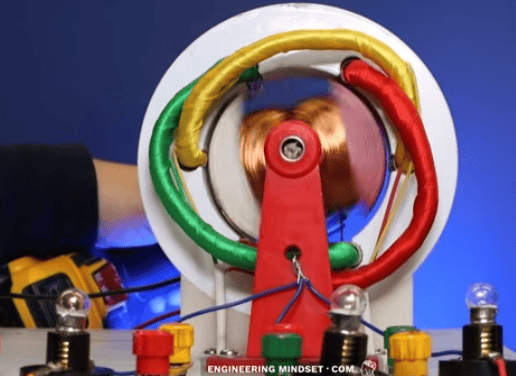
This is a generator, it produces electrical energy.
Inside the generator is the stator, and there’s a coil of wire on the top and bottom which are connected together forming a coil set. At the centre is the rotor which is attached to a magnet, and these can rotate together.
Anything can be used to rotate them, but here, wind turbine blades are used as an example.
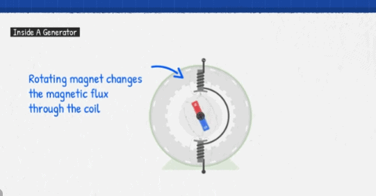
As this magnet rotates, its magnetic field will pass through the coil, so the coil experiences a changing intensity of the magnetic field as the magnetic field approaches and passes through it.
The changing magnetic field disturbs the electrons in the wire, inducing an electromotive force, or voltage, in the coil. If a circuit is connected to this coil, current will flow.
To prove that, we can connect a coil to a galvanometer. The dial moves when current flows in the circuit. A changing magnetic field will cause this.
Notice the dial deflects into the positive, or the negative as the magnet moves. Meaning the induced current is changing direction in the coil.
So what is happening here? Well, if we took a closed loop of wire and moved a magnet towards it, the magnetic field lines cut through the loop and induce a current, they cause a current to flow in this direction.
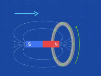
To understand why, remember that when current flows through a wire, it generates a magnetic field around the wire; if the current changes direction, so does the magnetic field.
So the induced current flows this way through the loop, because that will create an opposing magnetic field around the loop to try and fight the approaching magnet which is causing the disturbance.
Coils don’t like change, they want everything constant, and they will fight any change.
So when the magnet stops moving, the induced current stops and the opposing magnetic field also stops.
When the magnet moves in the opposite direction, the induced current flows in the opposite direction, because that creates an opposing magnetic field to try and prevent the change.
If the south pole is applied, the induced current and opposing magnetic field are reversed, again, to try and prevent the change.
Coming back to the galvanometer. We can see how the magnetic field is, essentially, causing the electrons to be pushed and pulled through the coil.
That is what’s happening with our generator. The changing magnetic field is basically pushing the electrons forwards and then pulling them backwards through the load, and this creates a sine wave pattern for both the voltage and the current.
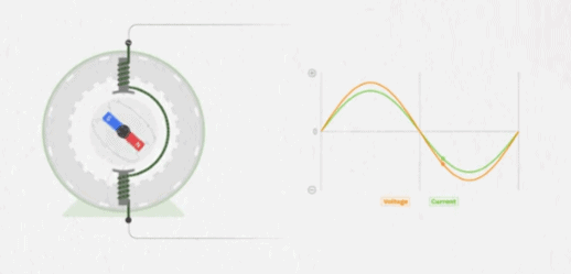
We can actually see this by connecting a portable oscilloscope to an outlet, the voltage follows a sine wave pattern.
This pattern repeats 60 times per second in north america and 50 times per second in europe and many other parts of the world.
And by using an isolated probe and a current clamp on an oscilloscope, we can see the current and voltage at the same time.
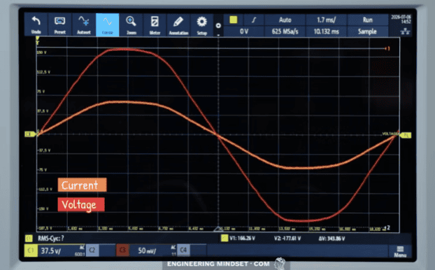
If we took a snapshot of this. We can see the values rise and fall with positive and negative values for both voltage and current with peak maximum values as well as points where both are zero.
So how can we find instantaneous power? And is it constant?
Well first we need to know the voltage and current.
We can find the instantaneous voltage at any point by using this formula.
If that looks confusing, I’ll break it down.
First we need to find the peak value.
We can easily measure this with an oscilloscope.
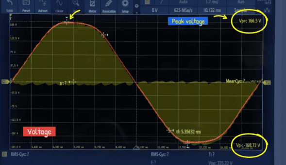
From that, we know the instantaneous value must be within this range of positive and negative peak values. But, where?
Well, that is what this sine value is for, it will find the exact value within the range.
To understand why, imagine a sine wave as a dot moving around a circle with a radius of 1.
The dots vertical position moves from zero, up to to 1, then back through 0 to negative 1 and then back to zero. So it can be anywhere from 1 to -1. That vertical position is the sine value.
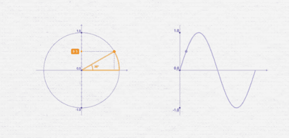
For example, if we stopped the angle at 30 degrees, we can see its vertical position is +0.5, meaning the wave is at 50% of its peak value.
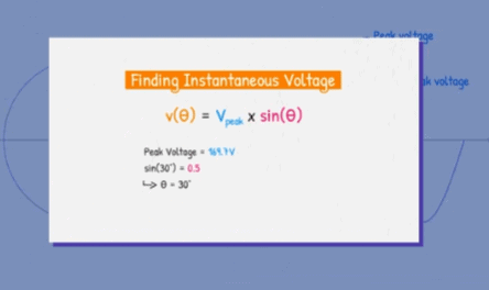
Now, using the formula, we have the peak, and we know the sine value. So we can calculate the voltage at that point. Easy.
But what if we don’t know the angle?
Well, the angle can also be calculated from the angular frequency and time.
We can easily measure the frequency of the supply,
and we can choose any time we want, therefore we can find the angle.
So, our formula for instantaneous voltage becomes this:
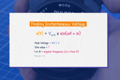
The lower case Omega symbol is the angular frequency, basically how fast the circle rotates, and we measure this in radians per second. So for a 60Hz supply, the angular frequency is calculated as this.
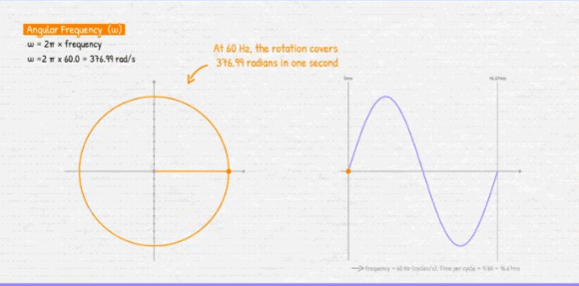
This is great when you have multiple cycles and you want to know the angle after a certain amount of time has passed, like 1.389 milliseconds for example.
We can then multiply the angular frequency and time, to get the angle in radians.
We could use radians, but I will convert it to degrees, and then find the sine value.
Now we just multiply this by the peak value, to find the instantaneous voltage. We can use that for any angle or time.
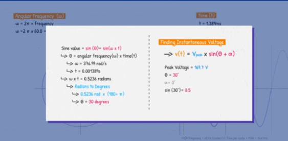
If you’re wondering about this part, sometimes the sine wave doesn’t start at zero, so we need to account for that, and we will see that in just a moment.
Notice that math like this can seem difficult, until someone breaks it down for you.
That’s why I like Brilliant. Their fully interactive personal tutor, Koji, is built right into the lesson and helps break down problems whenever your child gets stuck.
It doesn’t just give away the answer. It asks questions, gives hints, and guides students to figure it out for themselves, helping to build the confidence and problem-solving skills they’ll use long after they’ve finished the lesson.
What I really like, is that Brilliant also has thousands of lessons covering science, computers, AI and math. With learning paths designed by experts for everyone from grade 5 students through to college level. Each lesson is fully interactive through problem solving, which makes learning fun.
I think you’ll like this too. So, If you’re a parent, check out Brilliant. You can get started with Brilliant’s tutor for free, by clicking HERE. You can upgrade to Premium to unlock all courses. And right now, our viewers can save 20% off an annual subscription at Brilliant.org/TheEngineeringMindset
Ok, so, we have the voltage values, so we can use this formula to find the current. Although, I’ll use the simplified version.
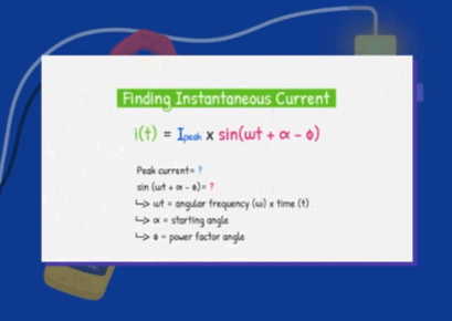
We just need to know the peak current, which is easy to calculate.
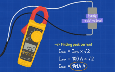
Then we can find the current and voltage at any point and I’ll include some examples here.
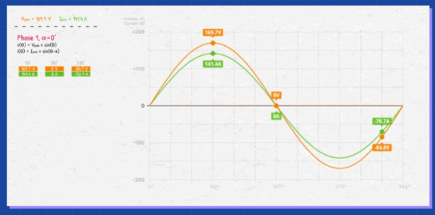
Then if we know the voltage and current, we can find the instantaneous power at any point also.
Notice the power isn’t constant, it occurs in pulses which are positive values only, because we have a resistive load in this example.
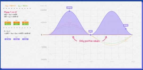
And the instantaneous power is pulsing at twice the supply frequency.
There are gaps where little or even no power is delivered, so we have to consider the average power to quantify this.
That is fine for something like a simple lamp. It just flickers a little, but the frequency is usually faster than the human eye can see, and the bulb remains hot, so it’s hardly noticeable.
Now, a generator and a motor work in similar but opposite ways. Basically, we input rotation, to produce electricity from the generator. But we input electricity to produce rotation from a motor.
However, if we tried to power an electric motor with single phase electricity, the motor wouldn’t start, it just vibrates. Because the magnetic field is just flipping polarity, the rotor doesn’t know which way to turn. Unless you give it a push, and it will continue in that direction.
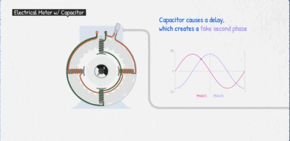
There are different ways to overcome this problem in the motor, but a capacitor and a second coil is an easy example.
The capacitor charges and discharges, causing a delay, which essentially creates a fake second phase that helps produce a rotating magnetic field, so the rotor will follow this and begin to rotate.
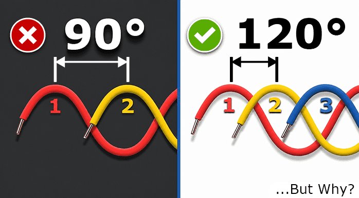
Instead of faking an extra phase, we could just add a second coil set at 90 degrees within, the generator. This coil set will experience the changing magnetic field at a slightly different time, so the voltage and current wave forms are delayed.
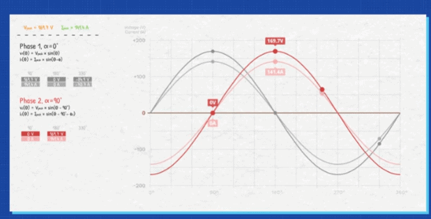
We already know the profile of the first phase. We can find the profile of the second phase using these formulas for voltage and current, which accounts for the 90 degree delay.
But, notice there’s still a gap in the profile. Will that be a problem? Well, we can calculate the power for the second phase but notice there’s an overlap between the profiles where both phases are providing power.
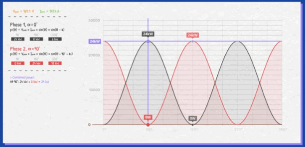
So, when combined, the gap disappears. To prove that, we can pick a point in the cycle and add the two phases together to find the total power. This value is the same at any point in the cycle.
So we have achieved constant power and we also doubled the amount of power being delivered, compared to the single phase average supply.
The problem is, we need 4 wires,
So if we want to send this over a long distance, we can deliver double the the power, but, we have doubled the material cost, compared to the single phase system.
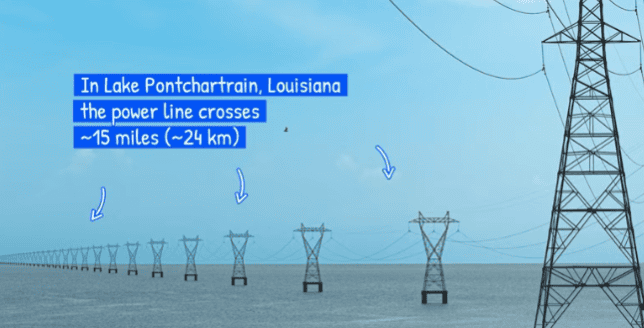
Sidenote, in reality, you might notice that aluminium or aluminum is used instead of copper for power transmission, that’s because it is cheaper and lighter.
It is also made from multiple strands and often has a steel core
for added strength to span those long distances.
But I’m using a solid core copper wire just to keep the maths simple for comparison.
So what can we do? One solution is to combine the neutral wires.
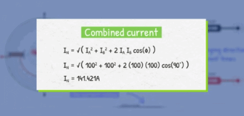
The problem is, the currents are changing direction at different times, so we need to account for this, otherwise the wire will overheat and catch fire.
We can calculate the combined current from both phases using this formula
So we need a slightly thicker wire to carry this current. But, this still results in a saving on the material cost, compared to using 4 thinner wires.
If we then consider a 2 phase motor, the magnetic field rotates, so we don’t need a capacitor as it can start by itself, but the magnetic fields still occur at right angles, so it’s not a smooth transition.
How can we improve this?
Well, we could add three sets of coils to the stator. These would need to be 120 degrees apart.
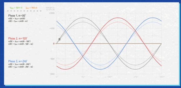
Each one produces a sine wave, with the voltages and currents rising and falling at different times, but they are evenly spaced out with no gaps.
We can calculate the voltage and current, at any point, for each phase using these formulas, which account for the rotational offset.
We could then calculate the power of each phase with these formulas.
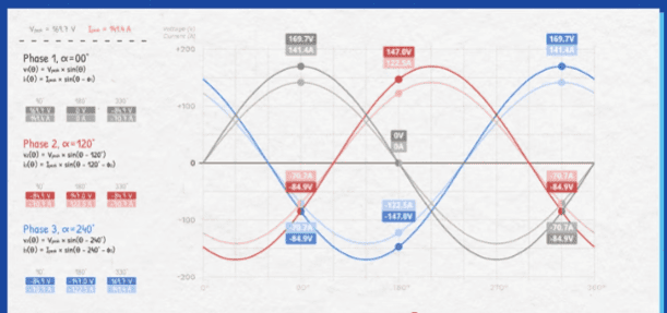
If we plot these we can see that the power of each phase pulses, it is not constant, but they do overlap.
At some instances only two phases are delivering power, while at other points, all three phases are working together.
You can see this clearly when we combine this data into a bar chart, the power is shifting between the phases.
You can download my excel sheets with interactive examples for each of the different setups shown in this article. Link here if you’re interested.
If we choose a point in the cycle, we can add the instantaneous power of each phase to find the total power. This value is the same at any point in the cycle so the power is constant.
Notice, the combined power is actually higher than the peak value of an individual phase. It is also the average of each phase combined.
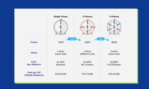
So, we can see the total power being delivered has increased again, compared to a single phase or a two phase system.
The problem with this design is that it needs 6 wires to distribute the power, so we have increased the power but we have equally increased the material cost.
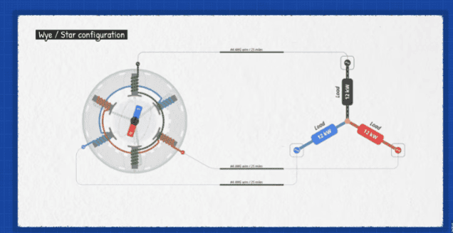
However, notice the pattern of the currents, They rise and fall at different times.
That means we could combine three of the wires together at the load and in the generator. The wires will take turns being each other’s return path. So, no neutral is needed, if the system is balanced.
That significantly reduces the material costs for the system.
So if we compare the different systems, a 3 phase system delivers 50% more power than a 2 phase system but costs around 8% less, and it delivers 3 times more power than a single phase system but only costs 50% more.
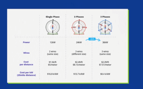
A 3 phase system also has the lowest cost per kW making it the clear winner.
But it gets even better.
Firstly because when we supply this to a 3 phase motor, we get a smooth rotation of the magnetic field. This allows the rotor to rotate smoothly with continuous torque which is why 3 phase motors are so efficient and reliable.
But, even better, 3 phase can also power single phase loads, it also gives us different configuration options which are used to provide different voltages, and we will see that in just a moment.
In reality, we generate and transmit power at much higher voltages. That’s because..
if the power station tried to deliver low voltages over a long distance, it would lose a lot of the power because of the resistance in the cables.
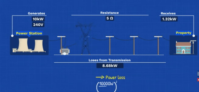
So a step up transformer is used to increase the voltage, and reduce the current during transmission, then a step down transformer reduces the voltage which increases the current again at the local distribution point. This lets us transfer the same amount of power over long distances with much lower losses.
That’s why power stations generate high voltages, and this increases further into the hundreds of thousands of volts for transmission, to keep the current low over long distances.
Then when it reaches the city a substation steps the voltage down, allowing industrial sites to connect into the grid, but otherwise it continues to a distribution substation where the voltage is again reduced and this is distributed out along the streets where commercial properties will connect to all three phases and the transformers supplying homes will either connect between a single phase and the neutral, or, between any two of the three phases, depending on the local setup.
But wait, where has that neutral come from?
Well the power is transmitted with just three wires and this connects to a step-down transformer with a delta primary, while the secondary side has a wye or star configuration.
From the centre point of the wye, we can connect a neutral wire. We usually also ground this point to provide a stable voltage reference.
This allows us to connect single phase loads from any phase to neutral, or we can connect larger equipment to all three phases.
If each single phase load is the same, the neutral current will cancel itself out, so no current flows along this wire back to the transformer.
However, usually the phases aren’t exactly equal, so the neutral provides a path to carry the imbalance from single phase loads back to the centre point of the transformers secondary side.
The primary side is a delta connection, the coils form a closed loop so the circuit is complete and current can return to the source with just 3 wires, no neutral is needed even when the current isn’t balanced.
The voltage is much higher so the current is lower but the same amount of power is transferred.
However, unbalanced loads can create problems, so engineers try to balance the local grid, spreading loads across phases.
If you look at the pole mounted transformers supplying a residential property, they will either connect to a phase and neutral, or they will be connected across two phases.
But, this is what causes confusion. Even though it’s connected across two phases, this is not a two phase system.
The transformer primary coil is connected directly across these two phase conductors, but the voltages of these are out of phase from each other. So which one will the coil use? Here’s the kicker, it doesn’t use either, it only sees the difference between them, which is a single phase connection. Notice this sine wave is at a different phase angle, with a higher peak, than the two supply phases.
From the peak, we can find the RMS voltage, which is supplied to the primary side of the transformer.
That is far too dangerous for use within a home, so the secondary side reduces this down to 240V rms between the two hot wires at either end of the coil.
However, the neutral is connected to the centre of the coil, allowing us to use either half of the coil, giving us half of the voltage.
They both provide sine waves, but they are inverted, because we are referencing from the centre of the coil to the outer edges.
The difference between them, gives us the peak single phase, which we use to find the rms voltage.
So, using two of the three phases provides a single phase supply, which can be reduced and used to power large appliances or it can be split into two, and used for small appliances.
So, two-phase worked, but three-phase delivered more power, used less material, gave smoother motors, and made it easier to supply different voltages, which is why it became the standard.