

Three way light switch circuits. In this article we’re going to be looking at three way switches for lighting circuits in north America. We’ll look at three different layouts depending on if you want the light fitting to be at the beginning, middle or end of the circuit.
Scroll to the bottom to watch the YouTube tutorial on 3 way switches
I’ve included a handy PDF wiring guide for 3 way switch circuits, which includes detailed illustrations of each circuit, step by step instructions and parts list. Keep it on your PC or phone and access them anywhere at any time. To see that, click here.
Warning
We’re covering the theory in this article but remember electricity is dangerous and can be fatal, you should be qualified and competent before carrying out any electrical work. Never work on hot/live electrical circuits.
How do three way switches work?
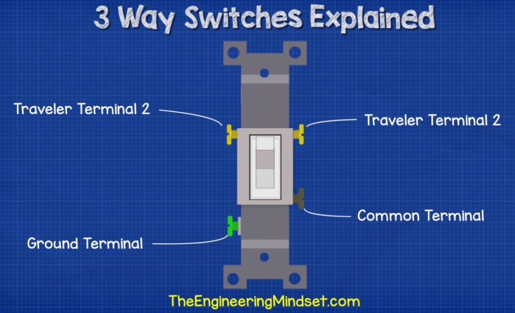
If we look at a 3-way switch we have 4 screw terminals. One is for ground, one is our common terminal and the other two our the traveler terminals.
Inside the switch we have a track which electricity can flow along, this is connected to the switch handle. When we flip the switch handle the track will flip between the two traveler terminals. This will change the path the electricity can take, and that’s how we will control the light.
Circuit design 1
The first circuit we’re going to look at is where the light fitting is last in the circuit.
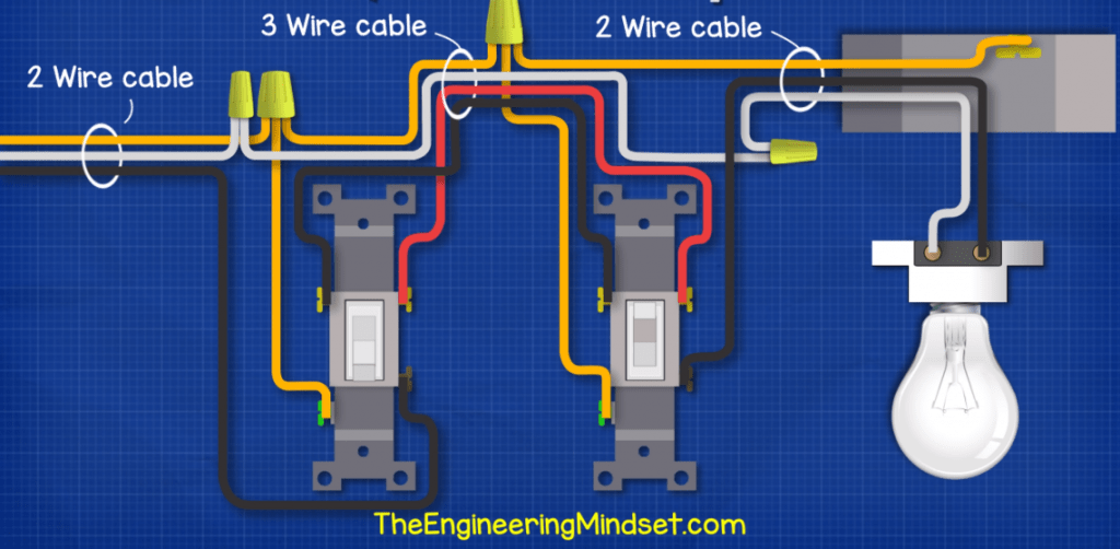
From the incoming power supply, we take the black hot wire and connect this into the common terminal of switch 1. We then run the black traveller wire from the left traveler terminal of switch 1 and over to the left traveler terminal of switch 2. Then we run the black hot wire from the common terminal of switch 2 over into the ceiling box and into the light fitting.Then we take the red traveler wire and run that from the right traveler terminal of switch 1 over to the right traveler terminal of switch 2.
Now for the incoming neutral, we run that into a wire connector which would sit within the switch box for switch 1. We then connect from this wire connector and run the white wire to a wire connector in switch box 2. Then we run the final white wire from the wire terminal of switch 2 over and through the ceiling box and to the light fitting which will complete the circuit.
To provide some safety we run a ground wire from the incoming supply and connect this into a wire connector in switch box 1.Then we run a ground wire from the ground terminal of switch 1 and connect this to the ground wire connector. We connect the next ground wire between the wire connector of switch box 1 and a wire connector in switch box 2. Then we run a ground wire from switch box 2 to the ground wire connector also. Finally as the ceiling box is metal we will run a ground wire from the ground screw in the box and connect this to the ground wire connector in switch box 2.
We have a 2 wire cable on the incoming power supply. A 3 wire cable between the two switches and another 2 wire cable from switch 2 over to the light fitting.
If we power this circuit, electricity comes in on the hot wire and passes across switch 1 and along the black traveler wire to switch 2, but switch two is in the up position so the circuit is broken and the light is off.
When we then flip switch 2 the tracks change direction and electricity can now flow across switch 2, through the light and back along the neutral wire.
If we were to flip switch 1, the electricity can now flow across switch one and into the red traveler wire but it stops at switch 2 as the tracks are disconnected. But by flipping switch 2 we again complete the circuit.
Circuit design 2
The next circuit we’ll look at is where the light fitting is between the two switches.
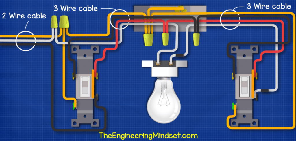
From the incoming power supply we will connect the hot black wire to the common terminal of switch 1. Then we run the black traveler wire from the left traveler terminal of switch one, over to a wire connector in the ceiling box. Then we run another black wire from the wire connector and connect this onto the left traveler terminal of switch 2.
We then run the red traveler wire from the right traveler terminal of switch 1 and connect this to a wire connector in the ceiling box. Then run another red wire from the wire connector and connect this to the right traveler terminal of switch 2.
Now we bring out neutral wire in from the incoming supply and connect that into a wire connector withing switch box 1. Then we run another neutral wire and run this from the wire connector, through the ceiling box and connect it to the light fitting. Then we run a third white wire from the other light fitting terminal and we run this to the common terminal of switch 2. We must mark both ends with black electrician tape to warn that this is intermittently hot.
Now to make the circuit safe we bring out neutral in to a wire connector. Then we connect the ground terminal of switch 1 into the wire connector. Then we run another ground from the wire connector and bring this to the wire connector within the ceiling box.
As the ceiling box is metal we will need to connect this to ground also using the ground screw. Then finally we want to ground switch 2 so we run a ground wire from the ground terminal and bring that over to the ground wire connector within the ceiing box.
We have a 2 wire cable on the incoming supply into switch box 1, then between both switches 1 and 2 and the light fitting we have 3 wire cables.
If we power this circuit we see that electricity can flow through the hot, across switch 1, through the ceiling box and to the terminal of switch 2, but the circuit is broken at switch 2 so the light is off.
When we flip switch 2 electricity can now flow across the switch, through the light and back through the neutral wire.
If we flip switch 1. Electricity will again be able to make it to switch 2 via the red traveler but it can’t get across switch 2.
But if we flip switch 2 then we complete the circuit and the light will turn on.
Circuit design 3
The final circuit we’ll cover is when the light fitting is before the two swtiches
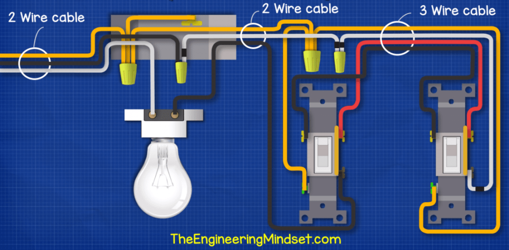
So for this circuit we’ll bring the incoming supply hot black wire into the ceiling box first and connect this into a wire connector. Then we run a white wire from that wire connector and connect this into a wire connector within switch box 1. We must mark the ends of this with black electrical tape to warn that it is intermittently live.
We then run another white wire from that wire connector and connect to the common terminal of switch 2, again marking the ends with black tape.
Now we run a red traveler wire from the right traveler terminal of switch 2 and connect this to the right traveler terminal of switch 1. Then we run a black traveler wire between the left traveler terminal of the two switches.
From switch 1 we will connect a black wire from the common terminal and connect this to the light fitting terminal. Now to complete the circuit we will bring our incoming neutral and connect this to the other light fitting terminal.
To make the circuit safe we bring out incoming ground wire and connect this to a wire connector within the ceiling box. As the ceiling box is metal we need to ground that using the ground screw. Then we run another ground between this wire connector and another within switch box 1. From there we will connect the switch ground terminal to the wire connector. And finally we run a ground wire the ground terminal of switch 2, to the ground wire connector.
We have a two wire cable for the incoming power into the ceiling box. A 2 wire cable to the first switch and a 3 wire cable between the two switches.
When we power the circuit, the electricity will flow through the hot wire and into the white wire over to switch 2. Then it travels along the red traveler but stops at switch 1. If we flip switch 2, the electricity can now flow over to and across switch 2 then through the light fitting and back through the neutral.
When we flip switch 1, the electricity can’t make it past the switch so the light is off. If we flip switch 2, the circuit is again complete so the light will turn on.


")
")

")


")


")

")

Three-Way 10! PDF?
I have a 3 way from my hall to a up stairs light and a toggle switch down in the cellar. What I am trying to do is change the switch down the cellar to a switch outlet so I can turn the switch off down the cellar and use the outlet with it own power so I can use the vacuum cleaner as well can you show me a video on how to wire. I purchased a 3 way switch outlet and broke the middle connection, so any help would be appreciated. Your You Tube videos are excellent.
You should show the world how to wire up 10 device residential Branch circuits. There’s no video on this.
Interested in the three way switching.
Can the information on three way switching be forwarded to me , thank you .
I am very interested in this information, your you tube page is very informative.
3 way pdf?
I have a three way switch that was previously hooked up, but one switch was disconnected. I have a black wire, a white wire and a red wire, no ground wire. The one that is already hooked up is white on top black on bottom and the red wire is hooked directly into the back of the light switch. The screws are all silver. I want to hook up the second switch, that switch has a brown screw and two copper colored screws. If I separate the three wires and use my tester, they all show hot. This is a light in the middle of the switches set up
I love this post.
Thanks so much sir
very interesting to know