Air Handling Units. In this article we’ll be learning how Air Handling units, or AHU’s, work. We’ll look at different examples of typical AHU’s along with animations for components such as dampers, heating and cooling coils, heat wheels, humidifiers, run around coils, heat exchangers and more, to help you learn HVAC engineering.
Scroll to bottom for YouTube video tutorial
🏆 Want more free HVAC courses? Create your free Danfoss Learning profile by clicking here
Join Danfoss Learning and gain access to hundreds of online courses on a wide variety of engineering topics. It’s free to sign up and you can log on anytime you want, which means you can learn at your own pace. Take exams and earn certifications for many courses.
Start learning now. Create your free Danfoss Learning profile – http://bit.ly/AHUDanfossLearning
So where do we find Air handling units?

Air handling units, which usually have the acronym of A.H.U are found in medium to large commercial and industrial buildings.
They are usually located in the basement, on the roof or on the floors of a building. AHU’s will serve a specified area or zone within a building such as the east side, or floors 1 – 10 or perhaps a single purpose such as just the buildings toilets. Therefore, it’s very common to find multiple AHU’s around a building.
Some buildings, particularly old high rise building, will have just one large AHU, usually located on the roof. These will supply the entire building. They might not have a return duct, some older designs rely on the air just leaking out of the building. This design isn’t so common anymore in new buildings because it’s very inefficient, now its most common to have multiple smaller AHU’s supplying different zones. The buildings are also more air tight so we need to have a return duct to regulate the pressure inside the building.
So, what is the purpose of an air handling unit?
Air handling units’ condition and distribute air within a building. They take fresh ambient air from outside, clean it, heat it or cool it, maybe humidify it and then force it through some ductwork around to the designed areas within a building. Most units will have an additional duct run to then pull the used dirty air out of the rooms, back to the AHU, where a fan will discharge it back to atmosphere. Some of this return air might be recirculated back into the fresh air supply to save energy, we’ll have a look at that later in the article. Otherwise, where that isn’t possible, thermal energy can extracted and fed into the fresh air intake. Again we’ll look at that later in more detail.
Lets have a look at a simple, typical designs, and then look at some more advanced ones.
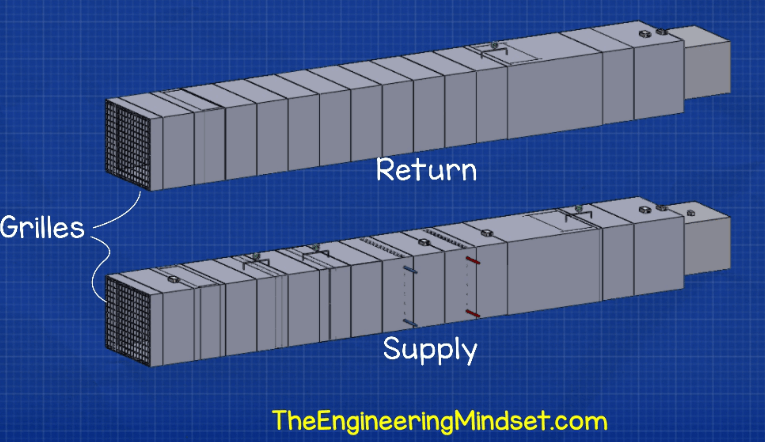
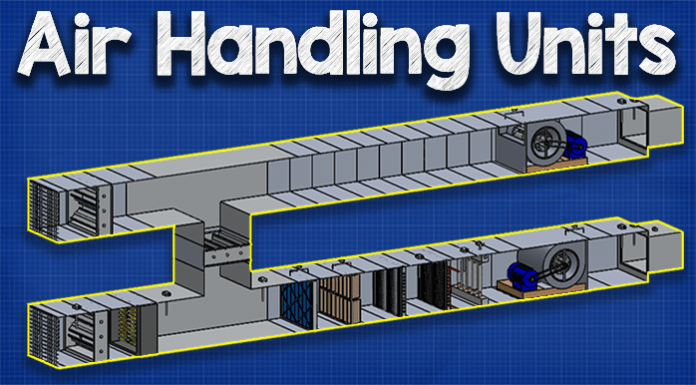
In this very basic model we have the two AHU housing for flow and return air. At the very front on the inlet and outlet of each housing we have a grille to prevent objects and wild life entering into the mechanical components inside the AHU.
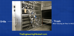
In this photo you can see that the AHU intake would have sucked in a whole bunch of trash if the grille wasn’t there, that’s why it’s important.
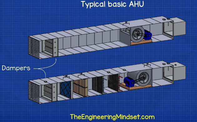
At the inlet of the fresh air housing and the discharge of the return air housing we have some dampers. The dampers are multiple sheets of metal which can rotate. They can close to prevent air from entering or exiting, they can open to fully allow air in or out, and it can also vary their position somewhere in between to restrict the amount of air that can enter or exit.

After the dampers we’ll have some filters. These are there to try and catch all the dirt and dust etc from entering the ahu and the building. If we don’t have these filters the dust is going to build up inside the ductwork and within the mechanical equipment, it’s also going to enter the building and be breathed in by the occupants as well as make the building dirty. So, we want to remove as much of this as possible. Across each bank of filters, we’ll have a pressure sensor. This will measure how dirty the filters are and warn the engineers when it’s time to replace the filters. As the filters pickup dirt, the amount of air that can flow through is restricted and this causes a pressure drop across the filters. Typically, we have some panel filters or pre-filters to catch the largest dust particles. Then we have some bag filters to catch the smaller dust particles. We’ve actually coved ahu filters in great detail previously. You can watch a video tutorial on that by clicking here.
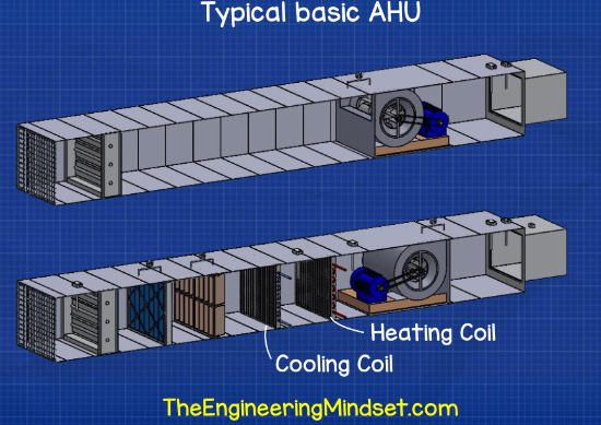
The next thing we’ll find are the cooling and heating coils. These are there to heat or cool the air. The air temperature of the supply air is measured as it leaves the AHU and enters the ductwork. This needs to be at a designed temperature to keep the people inside the building comfortable, this designed temperature is called the set point temperature. If the air temperature is below this value the heating coil will add heat to increase the air temperature and bring it up to setpoint. If the air is too hot then the cooling coil will remove heat to lower the air temperature and reach the setpoint. The coils are heat exchangers, inside the coil is a hot or cold fluid, usually something like heated or chilled water, refrigerant or steam. We’ve discussed these in detail previously, you can watch a video tutorial on that by clicking here.
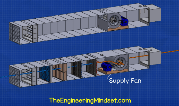
Next we’ll have a fan. This is going to pull the air in from outside and then through the dampers, filters and coils and then push this out into the ductwork around the building. Centrifugal fans are very common in old and existing AHU’s but EC fans are now being installed and also retro fitted for increased energy efficiency. Across the fan we’ll also have a pressure sensor, this will sense if the fan is running. If it is running then it will create a pressure difference, we can use this to detect a failure in the equipment and warn the engineers of the problem. We’ll also likely have a duct pressure sensor shortly after the fan, this will read the static pressure and in some ahu’s the speed of the fan is controlled as a result of the pressure in the duct, so we’ll also very often find a variable speed drive connected to the fan for variable volume systems. We’ve covered VAV systems separately, you can watch a video tutorial to that by clicking here.
Then we have the ductwork which will send the air around the building to the designed areas. We’ll also have some ductwork coming back which is brining all the used air from the building back to a separate part of the AHU. This return AHU is usually located near the supply, but it doesn’t have to be, it can be located elsewhere. If you want to learn how to size and design ductwork, you can watch a video tutorial by clicking here.
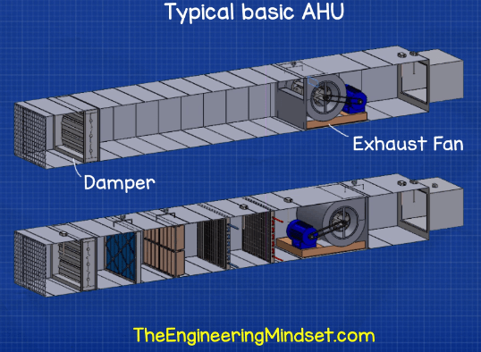
The return AHU in its simplest form has just a fan and damper inside. The fan is pulling the air in from around the building and then pushing it out of the building. The damper is located at the exit of the ahu housing and will close when the AHU turns off.
That’s a very simple and typical AHU. So what else might we find?
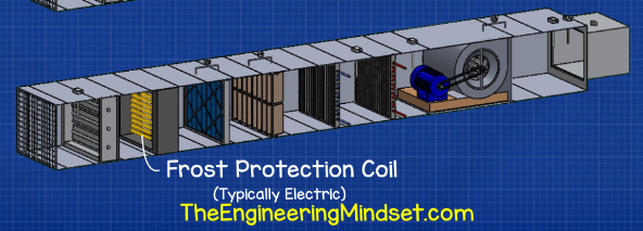
If you’re in a cold part of the world where the air temperature reaches freezing point or close to it. Then likely we’ll find a pre-heater at the inlet of the fresh air intake. This is usually an electrical heater. When the outside air gets to around 6*c (42.8F) the heater will come on and heat the air up to protect the components inside from frost. Otherwise this could freeze the heating and cooling coils inside and burst them.
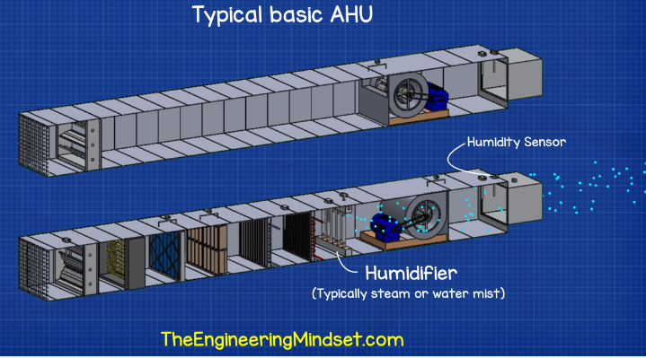
What about humidity control? Some buildings need to control the humidity of the air they supply into the building. We’ll find a humidity sensor at the outlet of the supply AHU to measure the moisture in the supply air, this will also have a setpoint for how much moisture should be in the air by design.
If the airs moisture content is below this value then we need to introduce moisture into the air using a humidifier, this is usually one of the last things in the AHU. This device will usually either add steam or spray a water mist into the air. Many standard office type building in northern Europe and north America have turned off their humidity units or uninstalled them to save energy. Although they’re still crucial for places like document stores and computer rooms.

If the air is too humid then this can be reduced through the cooling coil. As the air hits the cooling coil the cold surface will cause the moisture within the air to condense and flow away, you’ll find a drain pan under the cooling coil to catch the water and drain this away. The cooling coil can be used to further reduce the moisture content by removing more heat, but of course this will decrease the air temperature below the supply setpoint, if this occurs then the heating coil can also be turned on to bring the temperature back up, this will work although it is very energy intensive.
Energy recovery
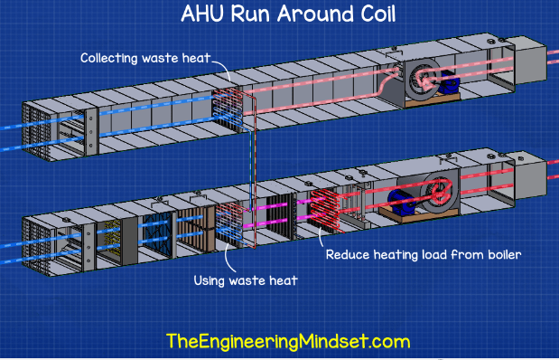
If the supply and extract AHU’s are located in different areas then a common way to recover some of the thermal energy is to use a run around coil. This uses a coil within both supply and return AHU’s which are connected via pipework. A pump circulates water between the two. This will pickup waste heat from the extract AHU and add this to the supply AHU. This will reduce the heating demand of the heating coil when the outside air temperature is below the supply setpoint temperature and the return air temperature is higher than the setpoint, the heat would otherwise be rejected to atmosphere. We’ll therefore need an air temperature sensor in the return AHU at the entrance and we’ll likely have air temperature sensors after the return coil as well as before the fresh air inlet. These will be used to control the pump as well as measure the effectiveness. As the pump will consume electricity, it is only cost effective to turn on if the energy saved is more than the pump would consume.
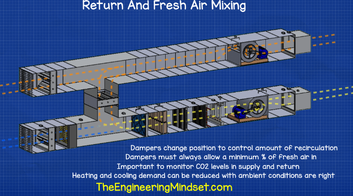
Another very common version we’ll come across is to have a duct sit in between the exhaust and the fresh air intake. This allows some of the exhaust air to be recirculated back into the fresh air intake, to offset the heating or cooling demand. This is safe and healthy to do but you will need to ensure the exhaust air has a low Co2 count so we need some Co2 sensors to monitor that. If the Co2 level is too high then the air can’t be re-used, the mixing damper will close and the all the return air will be rejected from the building. When in recirculation mode, the main inlet and outlet dampers will not fully close in this setup because we still need a minimum amount of fresh air to enter the building. We can use this in winter if the return air is warmer than the outside air and we can use this in summer if the return air is cooler than the outside air, respective to the supply setpoint air temperature, so we’ll also need some temperature sensors at the intake, return and just after the mixing region. Some buildings require 100% fresh air so this strategy can’t be used everywhere, local laws and regulations will dictate this.
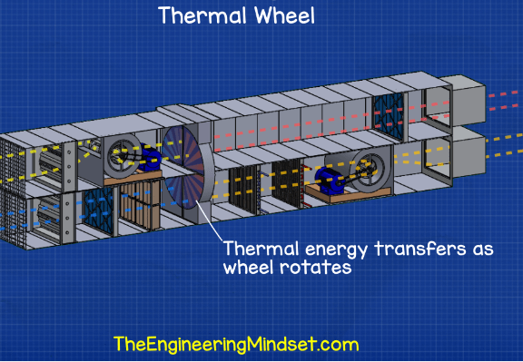
Another variation we might come across, is the heat wheel. This is very common in newer compact AHU’s. This uses a large rotating wheel, half of it sits within the exhaust air stream and half of it sits within the fresh air intake. The wheel will rotate, driven by a small induction motor, as it rotates it picks up unwanted heat from the exhaust stream and absorbs this into the wheels material. The wheel then rotates into the fresh air intake stream, this air is at a lower temperature than the exhaust stream so the heat will transfer from the wheel and into the fresh air stream which obviously heats this incoming air stream up and thus reduces the demand on the heating coil. This is very effective but some air will leak from the exhaust into the fresh air stream so this can not be used in all buildings.
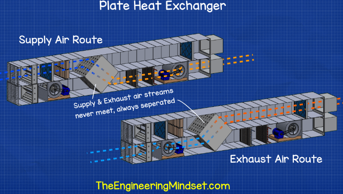
Another version we might come across is the air plate heat exchanger. This uses thin sheets of metal to separate the two streams of air so they do not come into contact or mix at all, the temperature difference between the two air streams will cause heat to transfer over from the hot exhaust stream through the metal walls of the heat exchanger and into the cold intake stream.






NECESSARY INFORMATION
Thank you for sharing this information, Its very useful for my school project
Very good presentation…i really understod and enjoyed it..thanks
Amazing post and valuable information. Thank You!
Very good intro on AHU concept
Nice, Useful & true articales for Air Handling Units Explained I appreciate your work and like it very much. Doing great work and keep it continue
Awesome Explained…..
Thanks Paul for writing one of the best articles on the internet about Air Units Handle (AHU). It was so fun to read that I being a newbie could also understand the entire article.
are you also a technician….?
Excellent Really to be appreciated for writing such a wonderful article on the AHU’s
very useful article about air handling unit performance. thanks
Thanks Paul Evans, words is too small for the value you add through your content, This is the best guide I have seen so far on the internet. Air Handling Units were easy to understand with comprehensive and easy explanation.
i need applicable range of the AHU machine. as an example when our design is 2000m3/hr and we install 5000m3/hr capacity machine is there any effect ?
no there is no any effect
The Subject very well Explained.
The wheel will rotate, driven by a small induction motor, as it rotates it picks up unwanted heat from the exhaust stream and absorbs this into the material of the wheel.
The article was very serious about the performance of industrial air conditioners. Thank you
This is very nice and valuable paper about air condition project.
Wish you the best
I appreciate your work and like it very much. The article was very useful. TNX
The article was very useful. Can it be made with less energy consumption?
Excellent
[…] This is how buildings maintain their fresh air, rather than having it become still and stagnant. A more in-depth explanation of this process can be found courtesy of The Engineering Mindset’s video on the subject. If that doesn’t do the trick, or if video is not your cup of tea, then there is an associated text version here. […]
many thanks
Thank you for your time .Well explained AHU’s components .
Brillliant presentation. well done
[…] We’ve covered air handling units in our previous article, view that HERE. […]
Wow …. Simply explained, thank you for sharing your knowledge…
great introduction to all the components in the AHU.
HOW DO YO DEFINE THE RIGHT OR LEFT HAND INSPECTION
many thanks really good content
Excellent explanation of air handling units. The diagrams and breakdown of components were especially helpful. It’s always great to see such detailed content that makes complex HVAC concepts more understandable. Thank you for sharing this!
Very interesting information thank you for sharing.