

Capacitors are used in many circuits for different purposes, so we’re going to learn some basic capacitor calculations for DC circuits.
Scroll to the bottom to watch the YouTube tutorial
Capacitors in DC Circuits
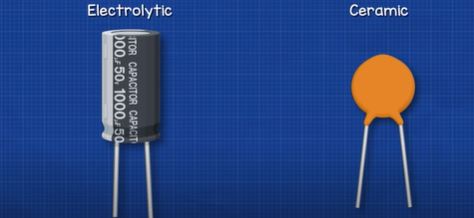
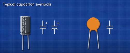
Capacitors typically look like this. We have an electrolytic and a ceramic type capacitor. The electrolytic is polarised meaning one side must be connected to the positive and one to the negative of the power supply. The ceramic type can generally be connected either way. On the side of the electrolytic capacitor, we find a dashed line indicating the negative side, the long lead also indicates the positive side of a brand-new capacitor. But, these are normally trimmed during installation though so don’t rely on this alone. These two capacitors are represented with symbols like these, notice the polarised capacitor has a small plus symbol indicating the positive side.
When connected to a DC supply, the voltage of the battery will push electrons into the capacitor and so the capacitor charges up to the same voltage as the battery. Capacitors are charged nearly instantly when connected directly to a battery, but we nearly always use a resistor, this will delay the charging time and later on in this article we will see how to calculate that.
Inside the capacitor, lots of electrons have built up on one side, they are prevented from moving across due to the insulating material between the two sides. As electrons are negatively charged, we therefore have a build up of charge on one side compared to the other, therefore we have a voltage difference between the two leads.
These electrons are held in place and the capacitor can hold this charge for long periods of time. When given a path, they will discharge until empty. Electrons do not pass through a capacitor; they simply build up inside and are then released.
The amount of charge stored in a capacitor is calculated using the formula Charge = capacitance (in Farads) multiplied by the voltage. So, for this 12V 100uF microfarad capacitor, we convert the microfarads to Farads (100/1,000,000=0.0001F) Then multiple this by 12V to see it stores a charge of 0.0012 Coulombs.
If we needed to store a charge of say 0.0002 coulombs then we just divide this by the voltage, in this case 12V to see we need 0.0024 Farads or 2,400uF microfarads.
We can calculate the energy stored in a capacitor using the formula = 0.5 multiplied by the capacity (in farads), multiplied by the voltage squared. =0.5xCxV^2
So if this 100uF microfarad capacitor was charged to 12V, we convert the microfarads to farads and then drop these numbers in to see it is storing 0.0072 Joules of energy.
=0.5 x 0.0001F x 12^2
=0.5 x 0.0001F x 144
=0.0072 Joules
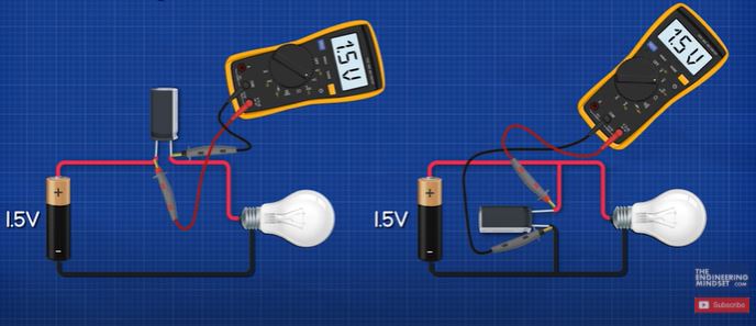
We know that the capacitor will charge up to the voltage of the battery. So, if we connected a capacitor like this, what will the voltage across the capacitor be? It will be 1.5V. If we connected a capacitor like this, what will its voltage be? It will also be 1.5V. These are two different ways to connect capacitors in circuits, either series or parallel. This will cause the capacitors to perform differently.
Parallel Capacitors
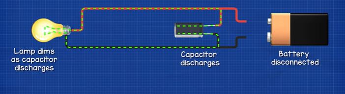
If we placed a capacitor in parallel with a lamp, when the battery is removed, the capacitor will begin to power the lamp, it slowly dims as the capacitor discharges. If we used two capacitors, we can power the lamp for longer.
Let’s say capacitor 1 = 10uF and capacitor 2 = 220uF. How do we calculate the total capacitance? That’s very simple, the answer is 230uF. The capacitors combine in parallel. So 10uF + 220uF = 230uF. We can keep adding more, such as a 100uF capacitor and the total is just the sum of all the capacitors. By placing them in parallel, we are essentially combining these to form a larger capacitor. That’s very useful, because if for example we needed a large 2000uF capacitor but we didn’t have one, we can just use more smaller capacitors such as 2x 1000uF of 4x 500uF etc. It’s also often used for filtering out noise and to provide more current in high demand circuits.
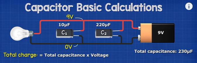
The total charge stored in parallel capacitors is just: charge = total capacitance multiplied by the voltage. So here we have a 9V battery and two capacitors with a total capacitance of 230uF. As this is parallel, this wire is 9V and this is 0V so both capacitors are charged to 9V. Therefore 0.00023 F multiplied by 9V = 0.00207 coulombs. And, with the three capacitors, we have 330uF (0.00033 F) multiplied by 9V = 0.00297 coulombs.
We can also calculate the charge of each capacitor individually. We just use the same formula for each capacitor, you can see the answers on screen for that.
Capacitor 1 = 0.00001 F x 9V = 0.00009 Coulombs
Capacitor 2 = 0.00022 F x 9V = 0.00198 Coulombs
Capacitor 3 = 0.0001 F x 9V = 0.0009 Coulombs
Total = 0.00009 + 0.00198 + 0.0009 = 0.00297 Coulombs
Series Capacitors
If we placed a capacitor in series with a lamp, when we press the switch it will illuminate but then becomes dimmer as the capacitor reaches the voltage level of the battery, and once it achieves this, the lamp will be off. Remember electrons can not flow through a capacitor because of the insulating material inside. The electrons are simply accumulating inside on one plate and as they accumulate they are rejecting an equal amount off the opposite plate. So, a current can only flow when the capacitor charges or discharges. Currently, with the battery removed there is no way for the capacitor to discharge so it will hold the voltage at the same level. It doesn’t matter if we connect or disconnect the battery, the lamp will not turn on. However, if we provide another path, when the switch is pressed, the capacitor can now discharge so the electrons can flow through the lamp and illuminate it. This will become dimmer as the capacitor discharges.
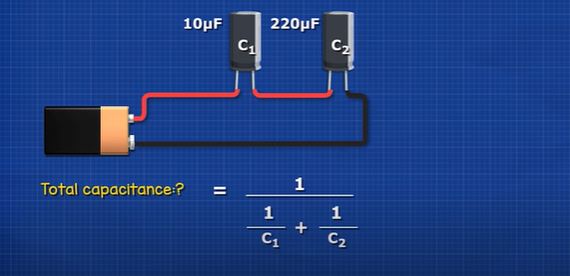
What if we had 2 capacitors connected in series, again, capacitor 1 is 10uF and capacitor 2 is 220uF. How do we find the total capacitance? For that we use this formula, it might look difficult but it’s actually very simple. All we need to do is input our capacitor values of 10 and 220uF. We can type it like this on our calculators or into excel. But with manual calculation, we do 1 divided by 10 which is 0.1 and 1 divided by 220 which is 0.00454. We add these together to get 0.10454 and then 1 divided by this gives a total of 9.56uF. Notice that the total capacitance is now smaller than the lowest value capacitor.
If we added a third capacitor of 100uF to the circuit, we get a total capacitance of 8.73uF. So, it has decreased even more. That’s because by combining these in series we’re essentially increasing the thickness of the insulating material, so the attraction of the negatively charged electrons to the positively charges holes on the opposite plate becomes weaker.
The total charge of the series capacitors is found using the formula charge = capacitance (in Farads) multipled by the voltage. So, if we used a 9V battery, we convert the microfarads to farads and see the total charge equals 0.00008604 Coulombs
(0.00000956F x 9V = 0.00008604 Coulombs)
The total charge for the 3 series capacitor circuit is there for 0.00007857 Coulombs
(0.00000873 x 9V = 0.00007857 Coulombs)
The charge held by each capacitor individually is very easy to calculate in series circuits. It’s the same as the total. Each capacitor holds the same number of electrons when in series. That’s because when we charged the capacitors, the current was exactly the same in all parts of the circuit. The same number of electrons that were pushed into one plate were pushed out of the opposite plate, so each series capacitor can only ever be charged to the same level. The smallest capacitor will therefore be the limiting factor.
However, because each capacitor can hold a different capacity, the voltage of each capacitor will be different. We find the voltage of each capacitor using the formula voltage = charge (in coulombs) divided by capacity (in farads).
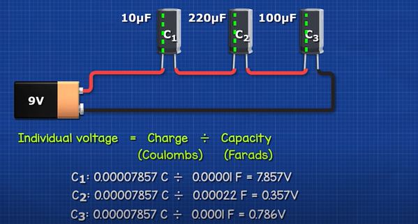
So for this circuit we see capacitor 1 is 7.8V, capacitor 2 is 0.35V and capacitor 3 is 0.78V. These combine to the total voltage of the battery, which is 9V.
Capacitor 1: 0.00007857 C / 0.00001 F = 7.857V
Capacitor 2: 0.00007857 C / 0.00022 F = 0.357V
Capacitor 3: 0.00007857 C / 0.0001 F = 0.786V
Total voltage = 7.857V + 0.357V + 0.786V = 9V
Capacitor Charge Time
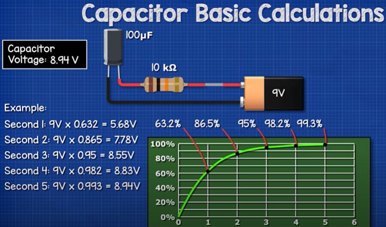
Let’s say we have a 9V battery, a 100uF capacitor, a 10 kiloohm resistor and a switch all in series. The capacitor is fully discharged and we read 0V across the two leads.
When we close the switch, the capacitor will charge. The voltage will increase until it is the same level as the battery. The voltage increase is not instant, it has an exponential curve. At first the voltage increases rapidly and then slows down until it reaches the same voltage level as the battery.
We split this curve into 6 segments, but we’re only interested in the first 5, because at the 5marker we’re basically at the full voltage so we can ignore anything past this. Each segment represents something called a time constant. Therefore, as we have 5 segments, we have 5 time constants, so it will take 5 time constants to charge the capacitor from 0 to just under 100%. All we need to do is calculate how long one time constant is and then multiply this by 5.
To calculate one time constant, we use this formula.
Time constant (in seconds) = the resistance (in Ohms), multiplied by the capacity (in Farads). So, we convert our resistor to ohms and our capacitor value to farads and see that 10,000 Ohms multiplied by 0.0001 Farads equals 1. So, in this example the time constant is equal to 1 second. Therefore 5 of these is 5 seconds. Meaning it takes 5 seconds for this capacitor to fully charge to 9V.
If the resistor was just 1,000 Ohms, the time constant would be 0.1 seconds, so it would take 0.5 seconds to reach 9V. If the capacitor was 1,000 microfarads it would take 50 seconds total. So as the capacitor size increases, the time taken increases. If the resistor value increases, the time taken also increases.
Coming back to our original circuit. We can therefor calculate the voltage level at each time constant. At point 1 the voltage is always 63.2%, point 2 is 86.5%, point 3 is 95%, point 4 is 98.2% and point 5 is 99.3%.
So in this example, after 1 second the capacitor voltage is 5.68V, after 2 seconds it’s 7.78V, after 3 seconds its 8.55V, after 4 seconds it’s 8.83V and after 5 seconds it’s 8.94V
If you need a more precise answer, we could calculate each point like this.
Point 1 = 9V-0V)x0.632 = 5.6880V
Point 2 = ((9V – 5.688V)x0.632)+5.68V = 7.7812V
Point 3 = ((9V-7.7812V)x0.632)+7.7812V = 8.5515V
Point 4 = ((9V-8.55V)x0.632)+8.5515V = 8.8349V
Point 5 = ((9V-8.8349V)x0.632)+8.8349V = 8.9393V
Remember because this is in series, the current of the circuit decreases, while the voltage of the capacitor increases. Once at full voltage, no current will flow in the circuit. If the resistor was a lamp, it would therefore instantly reach full brightness when the switch was closed, but then become dimmer as the capacitor reached full voltage.
Capacitor Discharge Time
When we provide a path for the capacitor to discharge, the electrons will leave the capacitor and the voltage of the capacitor reduces. It doesn’t discharge instantly but follows an exponential curve. We split this curve into 6 segments but we’re only interested in the first 5. At point 1 the voltage is always 36.8%, point 2 will be 13.5%, point 3 will be 5%, point 4 will be 1.8% and point 5 will be 0.7%.
For example, if we had a 9V battery, a lamp with a resistance of 500 Ohms and a 2000uF capacitor our time constant would be 500 Ohms multiplied by 0.002 Farads which is 1 second.
So, the very moment the battery is disconnected, the capacitor will be at 9V and as it’s powering the circuit, the lamp will therefore also be. After 1 time constant, in this case 1 second, the voltage will be 36.8% which is 3.312V, at 2 seconds it’s 1.215V, at 3 seconds it’s 0.45V, at 4 seconds it’s 0.162V and at 5 seconds it’s 0.063V. So the lamp will be illuminated for just under 3 seconds. Obviously becoming dimmer.


")
")

 Pressure Enthalpy Chart")


")

")

Helpful information 👍
Nice explanation!! Good for beginners thank you!!!
Can I join the group?
very fine
I’M ALWAYS WORKING ON 12VDC LED PROJECTS
IM LACKING IN KNOWLEDGE DEALING WITH AC DOOR BELL TRANSFORMERS AND 12 VDC LEDS
In the paragraph:
“If we needed to store a charge of say 0.0002 coulombs then we just divide this by the voltage, in this case 12V to see we need 0.0024 Farads or 2,400uF microfarads.”
Shouldn’t it be 0.0000166 Farads or 16.6uF?
First of all thank you.
‘We know that the capacitor will charge up to the voltage of the battery. So, if we connected a capacitor like this, what will the voltage across the capacitor be? It will be 1.5V. If we connected a capacitor like this, what will its voltage be? It will also be 1.5V. ”
You could point out that you are referring to the picture above the text and not anymore to the last example with 12V. Also you are repeating the same sentence.
what happen if i put 0.5v capacitor in 1.5v port?